
Views: 0 Author: Site Editor Publish Time: 2026-09-04 Origin: Site


Structural steel fabrication relies heavily on throughput and accuracy. Manual layout, center-punching, and mag-drilling act as primary bottlenecks that erode profit margins. Fabricators face a hard ceiling on production capacity, often stalling below 50 tons per week due to labor-intensive hole-making processes. Human error in measurements compounds the issue, leading to costly field rework. Inefficient material handling across varying lengths of steel slows down the entire shop floor. Transitioning to automated structural steel processing requires understanding the mechanical architecture, software integration, and operational limits of a modern CNC beam drilling machine. You must ensure the capital investment aligns with actual production demands. Upgrading your facility fundamentally changes how material flows through your shop, eliminating redundant crane lifts and manual staging.
Automation Replaces Manual Layout: CNC programming directly imports DSTV files from BIM software, eliminating manual measuring, marking, and the associated human error.
Throughput Scales with Spindle Configuration: Production capacity varies significantly (from 75 tons to over 150 tons per week) based on whether the machine utilizes a single rotating spindle or a multi-axis, 3-spindle design.
Stability Dictates Speed: High-speed carbide drilling requires rigid material holding; systems utilizing hydraulic clamping are mandatory for maintaining tool life and hole tolerance.
Integration Multiplies Value: Modern drill lines often combine drilling, scribing, stamping, and precision bandsaw cutting into a single continuous feed system to minimize crane lifts.
Efficient structural processing starts long before the drill bit touches the steel. Powered roller conveyors and cross-transfer decks stage raw structural profiles. They handle varying lengths and weights with ease, moving massive beams into the processing zone without manual intervention. Heavy-duty steel rollers support the dead weight of the steel, while cross-transfer systems allow operators to queue multiple beams laterally. This keeps the machine fed continuously without waiting for forklifts or overhead cranes to deliver the next piece.
Measuring systems track material position with extreme precision. Machines use rack and pinion drives, encoder-driven pinch rollers, or gripper carriages to pull the steel through the drilling window. These mechanisms ensure sub-millimeter accuracy along the X-axis. They maintain this tight tolerance regardless of the material size or surface condition. The system tracks position perfectly whether you process short base plates or 60-foot beams. Accurate material feeding eliminates the need for manual tape measures and compensates for natural material deviations like camber and sweep.
The gripper carriage system provides the most positive control over the material. It clamps onto the trailing edge of the beam and physically drags it through the machine. This eliminates any chance of slippage that can occur with pinch roller systems, especially when processing wet or oily steel. The carriage runs on precision linear guideways, driven by a massive servo motor and rack-and-pinion gear set, ensuring the physical position of the beam perfectly matches the digital coordinates in the CNC program.
The core drilling action happens along the Y and Z axes. The Y-axis controls vertical movement along the web. The Z-axis manages horizontal movement across the flanges. Servo motors drive heavy-duty ball screws to position the drill heads rapidly. This mechanical setup allows the machine to target any coordinate on the steel profile with absolute repeatability. The rigidity of these axes determines how aggressively you can push the cutting tools through the material.
Spindle configuration directly dictates your production speed. Single-spindle models must physically rotate around the beam to access the web and both flanges. This rotation adds seconds to every single hole cycle, which compounds into hours of lost production over a week. In contrast, 3-spindle models drill the top web and both side flanges simultaneously. This multi-axis approach maximizes efficiency for high-volume shops, allowing three holes to be completed in the time it takes a single-spindle machine to drill one.
Automatic tool changers (ATC) further minimize downtime. They switch automatically between drill bits, taps, and countersinks in seconds. A standard ATC magazine holds anywhere from four to twelve tools per spindle. When the CNC program calls for a different hole diameter or a tapping operation, the spindle retracts, drops the current tool into the carousel, grabs the new tool, and returns to the cutting position. This happens without any operator intervention, keeping the spindle turning and chips flying.
High-RPM drilling through thick structural steel generates intense vibration. You need a robust, heavy-duty machine frame to absorb these forces. Manufacturers use cast iron or heavily ribbed welded steel for the chassis. A rigid frame prevents micro-vibrations from transferring to the cutting tool. Vibration is the primary enemy of carbide tooling, causing the brittle inserts to chip or shatter prematurely.
A CNC beam drilling machine with hydraulic clamping secures the web and flanges tightly before any drilling begins. Massive hydraulic cylinders apply thousands of pounds of pressure directly adjacent to the drilling zone. This prevents material deflection during heavy chip loads. When a drill bit pushes into a half-inch thick web, the steel wants to flex away from the tool. Hydraulic clamps lock the material dead-center, forcing the tool to cut rather than push.
There is a direct correlation between rigid hydraulic clamping and extended tool life. Solid clamping prevents drill bit breakage and ensures perfect hole geometry. If the material shifts even a fraction of a millimeter during a high-speed drilling cycle, the lateral force will snap a solid carbide drill bit instantly. The hydraulic system also features variable pressure settings, allowing operators to dial back the clamping force when processing thin-walled structural tubing to prevent crushing the material.
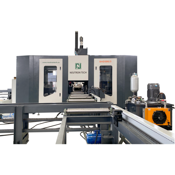
Modern fabrication demands rapid material penetration. A CNC high speed drilling machine for beams operates at aggressive parameters. Spindle RPMs often exceed 2,500 to 3,000 revolutions per minute. High feed rates push the tool through thick steel rapidly. Internal through-tool coolant systems are mandatory for these speeds. They pump an air/oil mist or flood coolant directly through the center of the drill bit to the cutting edge. This flushes chips out of the hole instantly and prevents thermal damage to the tool.
The industry has transitioned entirely from high-speed steel (HSS) to insert-style carbide tooling for structural applications. Carbide inserts offer significantly faster penetration rates. They withstand higher temperatures and maintain sharp edges longer. When an insert dulls, the operator simply rotates it to a fresh edge or replaces the small carbide tip, rather than replacing the entire drill body. This keeps tooling costs manageable while maximizing throughput.
Tooling Type | Average RPM | Penetration Rate | Coolant Requirement | Best Application |
|---|---|---|---|---|
High-Speed Steel (HSS) | 300 - 600 | Slow (2-4 inches/min) | External Flood | Older, low-rigidity machines; thin materials. |
Solid Carbide | 1,500 - 2,500 | Fast (10-15 inches/min) | Through-Tool | High-precision holes; rigid clamping required. |
Carbide Insert (Indexable) | 2,000 - 3,000+ | Very Fast (15-25 inches/min) | Through-Tool Mist | High-volume structural steel processing. |
Secondary spindle capabilities expand the machine's utility far beyond simple hole making. Modern drill lines handle thread tapping, countersinking, and light milling. You can easily produce slotted holes and copes without moving the beam to another station. The CNC controller interpolates the Y and Z axes simultaneously to mill out slots for expansion joints or structural connections, entirely eliminating the need for manual plasma cutting and grinding.
Layout work consumes massive amounts of labor in traditional shops. CNC drill lines eliminate this bottleneck completely. They use scribing tools or plasma markers to outline weldment locations directly onto the steel. The machine draws exact placement lines for clip angles, shear tabs, and stiffeners based on the imported 3D model. This automated layout entirely replaces manual layout personnel. Welders simply place the mating part on the scribed lines and weld, removing the need to read complex blueprints on the shop floor.
Part identification is equally critical for structural projects. Hard stamping or dot-peen marking systems imprint part numbers, job codes, and heat numbers directly into the steel. This ensures complete traceability through the galvanizing and assembly phases. Painted numbers burn off during welding or wash away in acid baths. Hard stamped characters survive the entire fabrication and erection process, ensuring the erection crew knows exactly where each beam goes on the job site.
The marking systems integrate directly into the spindle or operate as a separate hydraulic attachment. Dot-peen markers use a carbide stylus striking the steel rapidly to form alphanumeric characters. The depth of the mark can be adjusted based on the surface treatment the beam will receive. Deep marks are required for heavily galvanized parts, while lighter marks suffice for painted steel.
Fabricators rarely process just one type of steel. You need a machine that handles diverse structural shapes without requiring hours of mechanical changeover. Modern drill lines accommodate parts at vastly different lengths and dimensions. The clamping and measuring systems adapt to the specific profile automatically, reading the material width and height via laser sensors or physical probes before the drilling cycle begins.
Compatible profiles extend far beyond standard wide flange beams. The machine easily processes channels, angles, and flat bars. You can also run heavy base plates, structural tubing, and steel pipe. It even handles custom welded shapes. This versatility proves the machine can tackle almost any profile required by modern structural designs, allowing a single machine to process the entire bill of materials for a project.
Structural Profile | Typical Processing Requirements | Machine Adaptation |
|---|---|---|
Wide Flange Beams (I-Beams) | Web and flange drilling, scribing for stiffeners. | Standard 3-axis processing; full hydraulic clamping. |
C-Channels | Web drilling, single-side flange drilling. | One side spindle disabled; web spindle adjusts depth. |
Angle Iron | Asymmetrical leg drilling. | V-block clamping inserts; offset zero-point calibration. |
Square/Rectangular Tubing | Through-drilling both walls; tapping. | Reduced clamping pressure to prevent wall crushing. |
Flat Bar / Base Plates | Grid hole patterns; heavy countersinking. | Processed flat on the roller bed; web spindle only. |
You must establish baseline metrics before purchasing equipment. Evaluate your current weekly tonnage against machine capabilities. Entry-level machines generally process 50 to 75 tons per week. Heavy-duty, time-tested 3-spindle lines easily process 150+ tons per week. You need to match the machine's capacity to your bidding goals. Buying an undersized machine will leave you with the same bottlenecks, just automated ones.
Several factors impact overall cycle times. Spindle count is the most significant variable. Tool-change speed and automated material advancing also play major roles. A CNC beam drilling machine for steel structures must keep the steel moving. Every second the material sits idle cuts into your profit margin. Look closely at the rapid traverse rates of the spindles and the positioning speed of the material handling system.
You must also evaluate the software's ability to optimize tool paths. Intelligent CNC controllers sort the hole coordinates to minimize spindle travel and tool changes. If a beam requires ten holes of the same diameter scattered across the web, the software should drill them in the most efficient linear sequence, rather than jumping back and forth across the beam.
Fabricators must assess the trade-offs of standalone versus integrated systems. Coupling a drill line directly with a precision CNC bandsaw creates a robust system. You can also integrate a robotic plasma coper. This single continuous feed system minimizes material handling drastically. The steel moves from the cross-transfers, through the drill, directly into the saw, and out to the unloading zone without ever being touched by a crane.
Evaluate your floor space constraints carefully. Integrated systems require a longer linear footprint. You need space for the infeed conveyors, the drill cabin, the saw cabin, and the outfeed conveyors. However, the efficiency gained is massive. You eliminate intermediate material handling and staging bottlenecks. Redundant crane lifts disappear from your workflow. The steel enters as raw stock and exits fully drilled, marked, and cut to exact length, ready for the fitting bays.
If floor space is tight, a standalone drill line might be the only option. In this scenario, you must optimize the material flow between the drill and your existing cutting stations. Use heavy-duty roller conveyors to bridge the gap between machines, ensuring the steel never touches the floor between operations.
Hardware is useless without intelligent software driving it. Seamless integration with 3D detailing software is an absolute requirement. The machine must communicate flawlessly with programs like Tekla Structures, SDS/2, and Advance Steel. This digital thread connects the drafting room directly to the shop floor, ensuring the physical part matches the engineered model perfectly.
The workflow relies on exporting NC or DSTV files. You send these files directly to the machine's CNC controller over the shop network. This bypasses manual data entry completely. Operators do not program holes at the console; they simply load the file, verify the material dimensions, and press start. This eliminates the risk of an operator typing in the wrong coordinate and scrapping a costly beam.
Nesting software capabilities further optimize the process. The software arranges multiple shorter parts from a single long stock beam. It calculates the saw kerf and the required grip zones for the measuring carriage. This minimizes scrap and maximizes material yield. The operator loads a 60-foot beam, and the machine automatically processes and cuts five different parts from it, tracking the identity of each piece through the automated marking system.
Installing a beam drill line requires serious logistical planning. You must address the physical realities of the equipment footprint. Total length requirements are substantial. Infeed and outfeed conveyors often exceed 120 feet combined. You need this length to accommodate standard 60-foot structural steel beams safely on both sides of the processing cabin.
Concrete foundation requirements are strict. You cannot simply bolt these machines to a standard 6-inch warehouse floor. They require thick, reinforced concrete pads to handle the weight of the machine and the dynamic loads of moving steel. Proper leveling and anchoring are critical. A solid foundation supports heavy dynamic loads and maintains machine calibration over years of heavy use.
Excavate the existing shop floor to the manufacturer's specified depth, typically requiring a minimum of 12 to 18 inches of reinforced concrete.
Install heavy-duty rebar grids to prevent slab cracking under the dynamic loads of moving steel and machine vibration.
Position preset anchor bolts using a manufacturer-supplied template before pouring the concrete to ensure perfect alignment with the machine base.
Allow the concrete to cure completely for at least 28 days to reach maximum compressive strength before moving the heavy equipment onto the pad.
Perform final precision leveling using optical or laser transits while tightening the mounting hardware to lock the frame in place.
Automation shifts your labor requirements significantly. You no longer need armies of manual layout personnel wielding tape measures and soapstone. Instead, you need skilled CNC operators. These operators must manage automated workflows, understand tooling wear patterns, and troubleshoot software alerts. Training your existing staff is a critical step in successful implementation. The best operators often come from your existing layout crew, as they already understand structural steel blueprints and tolerances.
Routine maintenance demands consistent attention. You must manage hydraulic fluid levels and monitor spindle lubrication. Chip extraction systems require regular clearing. Coolant filtration systems need periodic cleaning to prevent clogs. Ignoring preventative maintenance leads directly to catastrophic downtime. A broken drill line stops the entire fabrication shop, as no steel can move to the welding bays.
Check hydraulic fluid levels and inspect high-pressure lines for leaks or abrasion daily.
Empty chip bins and clear the extraction augers to prevent metal shavings from jamming the cross-transfer mechanisms.
Verify the concentration and flow rate of the through-tool coolant system to prevent premature carbide insert failure.
Grease all linear guideways and ball screws according to the spindle manufacturer's exact hour-meter intervals.
Calibrate the material measuring encoders weekly to maintain sub-millimeter accuracy along the entire X-axis.
Request time studies from manufacturers using your own DSTV files to verify actual cycle times and validate production estimates.
Conduct site visits to operational facilities to observe robust systems running heavy structural steel under real-world conditions.
Evaluate the vendor's regional service network and spare parts availability to guarantee maximum machine uptime.
Map out your shop floor meticulously to ensure adequate space for extended infeed and outfeed conveyors before committing to a specific layout.
A: Throughput varies heavily by machine design. Single-spindle entry-level machines typically process 50 to 75 tons per week. Heavy-duty 3-spindle systems drill multiple faces simultaneously, easily exceeding 150 tons per week in a standard production environment.
A: Yes. Modern drill lines offer immense versatility. They easily process channels, angles, flat bars, and heavy base plates. Many systems also handle structural tubing and steel pipe of varying lengths and wall thicknesses.
A: Hydraulic clamping applies massive pressure to secure the steel profile. This eliminates material vibration and deflection during heavy chip loads. Rigid holding ensures precise hole placement and prevents expensive carbide tool breakage during high-speed operations.
A: A single-spindle machine uses one drill head that must physically rotate to reach the web and flanges sequentially. A 3-spindle system features three independent heads that drill the top web and both side flanges simultaneously, drastically reducing cycle times.
A: Yes. Imported CNC files dictate exact hole coordinates, scribe marks, and stamp locations. The machine performs all layout tasks automatically, entirely removing the need for manual tape-measuring, chalking, and center-punching.
A: These machines accept industry-standard DSTV and NC1 files. You export these files directly from 3D BIM detailing software, such as Tekla Structures, SDS/2, or Advance Steel, straight to the machine controller.
A: Many manufacturers utilize modular system designs. This allows you to add tandem precision sawing or robotic coping units later. However, you must plan your initial floor layout carefully to ensure adequate space for future integration.


