
Views: 0 Author: Site Editor Publish Time: 2026-09-01 Origin: Site


Transitioning from manual hole-making to automated systems solves major shop floor bottlenecks. High-volume metal fabrication often struggles with high scrap rates, inconsistent hole quality, and safety hazards. Relying on manual labor for heavy drilling limits production capacity and extends lead times. Upgrading to a CNC drilling machine directly eliminates these workflow constraints. This equipment replaces unpredictable manual processes with rigid, programmable accuracy. We will look at how automated drilling centers improve spindle uptime, reduce material waste, and increase overall throughput. You can evaluate specific machine configurations to match your structural fabrication requirements. Implementing these systems transforms raw material processing into a highly predictable, scalable operation.
Precision and Repeatability: Automated closed-loop systems drastically reduce scrap and eliminate the need for secondary rework, ensuring consistent part quality.
Operational Flexibility: Modern controls and rapid changeover capabilities make these machines highly adaptable for both high-volume production and complex, low-volume custom fabrication.
Application-Specific Configurations: Selecting the right architecture (CNC plate drilling machine, CNC angle drilling machine, or CNC beam drilling machine) aligns machine capabilities directly with specific structural fabrication requirements.
Favorable Return on Investment: Initial capital expenditures are systematically offset by reduced labor dependency, increased spindle uptime, lower maintenance overhead, and extended tool life.
Risk Mitigation: Successful implementation requires proactive assessment of CAD/CAM software compatibility, tooling requirements, and operator training curves.
Manual hole-making processes introduce massive hidden costs into metal fabrication workflows. Operators using magnetic drills or radial arm presses must manually layout hole locations. They center punch the mark, run a pilot drill, and finally execute the main bore. This multi-step process invites human error at every single stage. Misalignment by just a few thousandths of an inch can render a large structural component useless on the assembly floor. Out-of-tolerance holes require expensive weld-repair and redrilling. Sometimes they result in complete part rejection. Material waste accumulates rapidly when relying on manual positioning for complex multi-hole patterns on heavy steel plates.
Skilled labor shortages severely impact production capacity. Finding experienced machinists capable of maintaining tight tolerances over long shifts is difficult. When production relies entirely on manual labor, throughput is strictly limited by the physical endurance of the workforce. This dependency creates unpredictable lead times. It limits a facility's ability to scale operations during peak demand periods. You cannot simply speed up a manual operator without sacrificing quality or safety.
Workplace safety risks present another major operational hurdle. Manual heavy-duty hole making requires operators to wrestle with heavy steel plates, beams, and cumbersome tooling. The physical strain of operating manual presses and handling heavy material leads to operator fatigue. Fatigue directly correlates with a higher incidence of workplace injuries. Automating the drilling process removes the operator from the immediate hazard zone. It shifts their role from manual laborer to machine supervisor. This drastically reduces physical strain and improves overall shop floor safety.
Evaluating the success of a new machine installation requires establishing clear baseline metrics. Spindle utilization rate serves as a primary indicator of efficiency. Manual drilling operations often see spindle utilization rates below thirty percent. Most of the operator's time is spent on layout, tool changes, and material handling. Automated systems aim to push spindle utilization above eighty percent. The spindle should be turning and making chips for the vast majority of the shift.
Cycle time reduction and scrap percentage provide additional quantifiable metrics. Comparing the time required to complete a specific part manually versus automatically reveals the immediate throughput advantage. Setting realistic expectations for throughput increases depends heavily on material types, hole density, and part complexity. A component requiring hundreds of holes, such as a heat exchanger tube sheet, will see an exponential decrease in cycle time. Parts with only a few holes may show smaller cycle time improvements but will still benefit from absolute positional accuracy. Understanding these variables allows facility managers to accurately project production capacity.
Modern automated drilling centers rely on closed-loop feedback systems to guarantee exact hole placement. These systems utilize precision linear glass scales and rotary encoders. The encoders continuously monitor the physical position of the spindle and the cutting tool. They feed this positional data back to the servo drives in real-time. If a deviation occurs due to cutting forces or thermal expansion, the control system instantly compensates. This closed-loop architecture eliminates the backlash and positioning errors inherent in older, open-loop lead screw designs.
Rigid machine frames further enhance this precision. Heavy cast iron or stress-relieved steel weldments absorb the intense vibrations generated during heavy-duty hole making. This rigidity prevents the drill bit from wandering upon initial contact with the material. Automation entirely eliminates human error across complex, multi-hole patterns. Once the program is verified, the machine will drill the thousandth part with the exact same dimensional accuracy as the first. This repeatability is mandatory for tight-tolerance geometries where mating parts must align perfectly during final assembly.
Rapid automatic tool changers (ATC) drastically reduce non-cutting time. An operator manually changing a large drill bit, securing the chuck, and setting the tool height can take several minutes. A servo-driven ATC executes this same sequence in seconds. This rapid changeover is particularly beneficial for parts requiring center drilling, standard drilling, chamfering, and tapping in a single setup. The machine swaps tools seamlessly without operator intervention.
Optimized feed rates maximize material removal. The machine control precisely matches the spindle RPM and downward feed rate to the specific cutting tool and material hardness. This optimization prevents the tool from rubbing or stalling. It ensures a continuous, aggressive cut through tough materials like A992 structural steel. Multi-axis capabilities allow simultaneous operations without manual part repositioning. The spindle moves dynamically across the X, Y, and Z axes to reach every programmed coordinate. This eliminates the need for operators to unclamp, shift, and reclamp heavy workpieces.
Automated systems easily adapt to high-mix, low-volume production environments. Rapid program changeovers allow a facility to run a batch of heavy flanges in the morning and switch to custom base plates in the afternoon. Intuitive interfaces and conversational programming enable operators to input hole patterns directly at the machine control. This bypasses the need for complex offline CAM programming for simple 2D geometries.
Managing complex geometries and varying hole diameters happens seamlessly. The machine reads the program, selects the appropriate tool from the carousel, and adjusts the cutting parameters automatically. It handles bolt circles, grid patterns, and staggered layouts without requiring multiple manual setups or custom drill jigs. This flexibility allows fabrication shops to accept a wider variety of jobs. You can respond quickly to urgent customer requests without disrupting the entire production schedule.
Predictive tool wear monitoring prevents catastrophic tool failure. The machine control continuously monitors the spindle motor load. As a drill bit dulls, the torque required to push it through the material increases. When the spindle load exceeds a pre-set threshold, the machine automatically pauses the cycle and alerts the operator. This prevents the drill from snapping inside the workpiece. Broken tools often result in scrapped parts and expensive downtime while the broken carbide is extracted.
Consistent chip evacuation plays a massive role in tool life and hole quality. Automated peck drilling cycles periodically retract the drill to break and clear chips. High-pressure coolant systems flush these chips out of the hole instantly. Proper chip evacuation prevents the chips from recutting. Recutting causes surface scoring and internal hole defects. It also prevents heat buildup, keeping the cutting edge sharp and significantly extending the lifespan of expensive carbide tooling.
Identifying the ideal use cases for a CNC plate drilling machine involves looking at flat, heavy-duty components. These machines excel at processing tube sheets, baffle plates, heavy flanges, and large structural base plates. The architecture is designed specifically to handle large, heavy sheets of steel that require high-density hole patterns.
Key evaluation dimensions include table size and clamping mechanisms. The table must accommodate the maximum plate dimensions processed by the facility. Hydraulic clamping mechanisms are non-negotiable for heavy work. They apply massive downward pressure to secure the plate flat against the table. This prevents the material from bowing or vibrating during heavy drilling, which can shatter brittle carbide tools. Multi-spindle options allow for high-volume nesting. A dual-gantry system with multiple spindles can drill several identical parts simultaneously out of a single large plate.
The primary use cases for a CNC angle drilling machine center around long structural profiles. These systems are indispensable for manufacturing transmission towers, telecommunication structures, and structural steel frameworks. Angle iron requires specialized handling and processing to maintain accuracy over long lengths.
Integration of automated feeding systems is a primary evaluation metric. Precision pinch rollers or servo-driven gripper carriages feed the raw angle iron through the machine. This eliminates manual material pushing and ensures accurate linear positioning. Facilities must also evaluate the trade-offs between punching and drilling. Punching is exceptionally fast for thinner materials. Drilling is mandatory for thicker structural steel to avoid micro-fractures and material deformation around the hole. Many advanced angle lines incorporate both punching and drilling heads to maximize versatility.
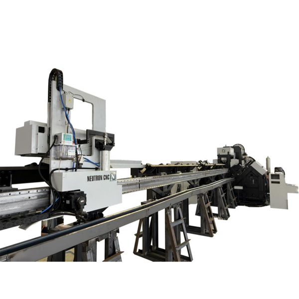
A CNC beam drilling machine is engineered specifically for heavy structural profiles. Ideal applications include processing I-beams, H-beams, steel channels, and large rectangular tubes. These components form the backbone of commercial buildings, bridges, and industrial frameworks.
Multi-spindle configurations define the efficiency of these machines. A high-end beam drill features three independent drilling axes. This allows the machine to drill the web and both flanges of an I-beam simultaneously. Simultaneous drilling eliminates the need to rotate or flip massive beams using overhead cranes. Flipping beams is slow and highly dangerous. Seamless integration with automated material handling systems creates a continuous flow of material. Motorized cross-transfers and input/output roller conveyors move massive steel profiles through the fabrication cell with zero manual lifting.
Understanding the mechanical differences between milling and drilling dictates proper machine selection. Drilling generates purely axial cutting forces. The thrust is directed straight down the Z-axis into the material. The machine frame and spindle bearings must withstand massive downward pressure. Pushing large diameter spade drills or indexable insert drills through thick steel requires immense rigidity.
Milling generates radial and lateral cutting forces. The tool cuts on its side, pushing against the X and Y axes. While a Vertical Machining Center (VMC) can drill holes, its spindle and bearing architecture is optimized for lateral milling loads. It is not built for heavy axial thrust. A dedicated drilling center features heavy-duty thrust bearings and a massive Z-axis quill. This design absorbs vertical drilling forces without deflecting.
High-volume hole making dictates the need for a specialized drilling center. If a part requires heavy material removal via face milling or complex 3D contouring, a VMC is required. If a part is primarily flat and requires hundreds of deep, large-diameter holes, a VMC will be painfully slow. A dedicated drilling machine will push a drill through steel significantly faster than a standard milling machine.
Conducting a cost-per-part analysis clarifies the decision. Compare the cycle time of a dedicated drilling center against a multi-purpose VMC for a specific hole-intensive part. The dedicated machine will typically feature higher spindle torque at lower RPMs. It will also utilize high-pressure through-tool coolant. These features allow for aggressive feed rates that a standard VMC simply cannot match. The resulting reduction in cycle time lowers the overall cost-per-part.
Feature | Dedicated CNC Drilling Machine | CNC Milling Machine (VMC) |
|---|---|---|
Primary Cutting Force | Axial (Z-axis downward thrust) | Radial / Lateral (X and Y-axis side cutting) |
Spindle Architecture | High torque at low RPM, heavy thrust bearings | High RPM, optimized for lateral loads |
Hole Making Speed | Exceptionally fast, optimized for aggressive feeds | Moderate, limited by Z-axis rigidity |
Best Application | Tube sheets, structural steel, heavy flanges | Complex 3D contours, pockets, face milling |
Material Handling | Integrated with large tables or roller feeds | Enclosed, limited by table enclosure size |
Breaking down the true cost of acquisition requires looking beyond the sticker price of the machine. The initial capital expenditure includes the machine price, freight, and specialized rigging required to move heavy equipment into place. Installation often requires facility modifications. You may need to pour reinforced concrete foundations to support the machine's weight and prevent vibration transfer. Upgrading electrical drops and compressed air lines is also frequently necessary to meet the machine's utility requirements.
Calculating the payback period relies on projected throughput increases and reduced scrap rates. When a machine reduces a ten-hour manual drilling job to a two-hour automated cycle, the labor savings are immediate. The reallocation of manual labor allows skilled workers to focus on complex welding or assembly tasks rather than basic hole making. The virtual elimination of scrapped parts due to positional errors directly protects profit margins. These combined factors typically result in a highly favorable payback period for high-volume fabrication shops.
Evaluating optional features like through-spindle coolant (TSC) systems is necessary for maximizing returns. TSC pumps high-pressure cutting fluid directly through the center of the drill bit to the cutting edge. This instantly evacuates chips and prevents heat buildup. While a TSC system increases the initial purchase price, it drastically extends the life of expensive solid carbide and indexable drills. The reduction in consumable tooling costs quickly offsets the initial investment in the coolant system.
Factoring in routine maintenance ensures long-term reliability and protects the investment. Automated machines require consistent upkeep. Linear guides and ball screws must be properly lubricated to maintain positional accuracy. Coolant filtration systems require regular cleaning to prevent chip sludge from damaging high-pressure pumps. Establishing a strict preventative maintenance schedule prevents unexpected breakdowns. It maximizes spindle uptime and ensures the machine continues to deliver value for decades.
A significant risk during implementation involves post-processor compatibility issues. Engineering departments generate part designs in CAD and toolpaths in CAM software. The post-processor translates these toolpaths into the specific G-code dialect understood by the machine's control unit. If the post-processor is flawed or incompatible, communication breaks down. The machine may interpret commands incorrectly. This leads to scrapped parts or severe machine crashes.
Mitigating this risk requires verifying control system compatibility prior to purchase. Ensure the machine utilizes an industry-standard control, such as Fanuc, Siemens, or Fagor. Work closely with the machine tool builder and your CAM software provider to develop and test the post-processor before the machine arrives on the shop floor. Running simulation software to verify G-code offline further prevents costly collisions. It ensures a smooth transition from engineering to production.
Machine underutilization due to a lack of in-house programming expertise is a common risk. Transitioning operators from manual drill presses to advanced automated systems presents a steep learning curve. If operators are intimidated by the control interface or lack the skills to set up new jobs efficiently, the machine will sit idle. This underutilization directly impacts the projected return on investment.
Implementing phased training programs bridges this skills gap. Leverage modern, user-friendly Human-Machine Interfaces (HMIs) equipped with conversational programming. Conversational controls allow operators to select hole patterns, input dimensions, and define material thickness using graphical menus rather than writing raw G-code. This intuitive approach drastically reduces setup time. It empowers operators to confidently run the machine. Continuous training and support from the machine builder ensure the team maximizes the equipment's capabilities.
Audit your current manual drilling workflows to document exact cycle times and identify specific bottlenecks.
Compile a list of your most frequently processed material profiles and maximum dimensions to determine the required machine architecture.
Request test cuts and cycle-time estimates from machine builders using your actual part drawings.
Evaluate your shop floor layout to confirm adequate space for automated material handling and safe operator access.
A: The primary advantage is the elimination of human error and manual layout time. Automated systems use closed-loop feedback to position the drill exactly on coordinate. This ensures perfect repeatability, drastically reduces cycle times, and virtually eliminates scrapped parts due to misalignment.
A: A plate drilling center features heavy-duty thrust bearings optimized for massive axial downward forces required for large-diameter hole making. It utilizes hydraulic clamping to hold large steel sheets flat. A VMC is optimized for lateral milling forces and smaller enclosed work envelopes.
A: Yes. Modern beam drilling centers equipped with automatic tool changers can seamlessly switch from drilling to tapping, countersinking, and light slot milling. They are not designed for heavy face milling or complex 3D contouring.
A: Payback periods vary based on production volume. High-volume structural fabricators often see returns within twelve to twenty-four months. This is driven by massive reductions in labor hours, faster throughput, and the elimination of rework caused by manual layout errors.
A: Modern controls feature conversational programming interfaces. Operators can input hole patterns and dimensions directly at the machine using graphical menus. This eliminates the need for offline CAM programming, making it highly efficient to set up and run low-volume or custom parts.
A: Through-spindle coolant pumps high-pressure fluid directly through the center of the drill to the cutting edge. This instantly flushes chips out of deep holes, prevents heat accumulation, allows for much more aggressive feed rates, and significantly extends the life of carbide tooling.


