
Views: 0 Author: Site Editor Publish Time: 2026-09-08 Origin: Site


In structural steel fabrication, profit margins depend on throughput efficiency and hole-making precision. Bottlenecks at the drill line cause immediate delays during assembly and erection. Relying on manual layout, magnetic drills, or outdated punch presses leads to dimensional inaccuracies, high labor hours, and severe production limits when processing heavy structural profiles. Fabricators facing tight tolerances and demanding schedules cannot depend on manual intervention to hit daily tonnage targets.
Transitioning to a modern, automated beam drilling machine requires evaluating spindle configurations, clamping mechanisms, multi-process capabilities, and software integration. You must ensure the equipment aligns with your facility's specific tonnage and profile variability. Understanding the mechanical capabilities and software ecosystems of these systems eliminates layout errors and maximizes production floor throughput.
Production Alignment: Selecting between single-spindle and multi-spindle configurations must be driven by your facility's monthly tonnage and the complexity of hole patterns in your typical projects.
Tooling & Speed: A true high speed beam drilling machine requires specific RPM capabilities, through-tool coolant, and rigid construction to utilize carbide tooling effectively, drastically reducing cycle times compared to High-Speed Steel (HSS).
Stability is Critical: Utilizing a beam drilling machine with hydraulic clamping is non-negotiable for heavy structural work, as it eliminates vibration, ensures positional accuracy, and prevents premature tool wear.
Establishing baseline metrics for acceptable cycle times per beam and required hole tolerances dictates your equipment selection. Structural steel fabrication demands strict adherence to dimensional accuracy, particularly when meeting AISC standards for bolted connections. Oversized, elongated, or misaligned holes compromise structural integrity and force erection crews into field modifications. You must define your target daily tonnage and calculate the exact hole-making volume required to sustain that output. High-volume operations require cycle times measured in seconds per hole, necessitating advanced spindle technology and rapid material positioning systems. When dealing with slip-critical connections, the hole diameter tolerance is unforgiving, meaning your machine must maintain absolute rigidity during the plunge.
Assess the exact mix of materials processed daily on your shop floor. The equipment must comfortably accommodate the maximum and minimum dimensions of your typical structural profiles. This includes heavy W-shapes, I-beams, C-channels, L-angles, and rectangular hollow sections (RHS). Consider the maximum weight per foot of the heaviest profiles you process, as this dictates the required load capacity of the roller conveyors and the structural rigidity of the machine frame. Processing asymmetrical profiles like angles or channels often requires specialized clamping sequences or datum line adjustments. The machine's control system must handle these variations seamlessly without requiring the operator to manually shim or adjust the material.
Determine exactly how the new equipment will fit into your current material flow. A high-performance drill line is only as effective as the material handling system feeding it. Evaluate the pathway from raw material staging in the yard through the saw or coping station, and finally to welding and painting. If the drill processes material faster than the downstream welding stations can consume it, you create a new bottleneck. Proper integration requires planning for cross-transfer decks, buffer zones, and synchronized infeed/outfeed roller conveyors to maintain a continuous, uninterrupted flow of steel through the facility. Drag chains or lift-and-carry systems move beams laterally, keeping the main conveyor fed without waiting on overhead crane availability.
Single-spindle configurations feature one robust drill head mounted on a rotating axis or a moving gantry. The machine processes the web and flanges sequentially, rotating the spindle or repositioning the material to access different faces of the profile. This design works well for low-to-medium volume fabricators or facilities dealing with severe space constraints. It also serves as a supplementary machine for custom, one-off parts that would otherwise interrupt the flow of a main production line. While cycle times are longer due to the sequential processing, the mechanical simplicity results in a highly reliable and space-efficient footprint.
Multi-spindle systems utilize three independent drill heads—one dedicated to the web and two dedicated to the flanges. This allows an H beam drilling machine to process all three sides of a structural profile simultaneously. By eliminating the need to rotate a single spindle or reposition the heavy steel beam, these machines drastically reduce overall cycle times. They are the definitive choice for high-volume structural steel fabricators requiring maximum throughput. The independent axes allow for different hole diameters and patterns to be executed on the web and flanges at the exact same time, maximizing spindle utilization and minimizing idle time.
These specialized units are built with high-torque, high-RPM direct-drive spindles designed specifically to run indexable carbide tooling. A high speed beam drilling machine operates at speeds and feed rates that traditional equipment simply cannot sustain. They fit best in operations where cycle time reduction drives production efficiency and where material handling automation is already highly optimized. The rigid frame construction absorbs the intense cutting forces generated by carbide inserts, ensuring precise hole geometry even at maximum feed rates. These machines often feature spindle motors exceeding 20 horsepower to maintain torque during aggressive drilling sequences.
Tandem lines integrate the drilling unit directly with a CNC band saw, circular cold saw, or robotic thermal coping unit. These systems share a single measurement carriage and material handling conveyor. By combining these processes, facilities eliminate intermediate crane lifts and staging between the cutting and drilling phases. This maximizes floor space efficiency and significantly reduces the labor hours associated with material handling. The CNC control synchronizes the datum points for both the drill and the saw, ensuring perfect dimensional accuracy from the end-cut to the first hole pattern.
Configuration Type | Spindle Count | Primary Advantage | Best Suited For | Relative Cycle Time |
|---|---|---|---|---|
Single-Spindle | 1 | Compact footprint, mechanical simplicity | Low-medium volume, space-constrained shops | Slowest (Sequential processing) |
Multi-Spindle (3D) | 3 | Simultaneous processing of web and flanges | High-volume structural fabricators | Fast (Simultaneous processing) |
High-Speed Carbide | 1 to 3 | Maximum RPM for indexable carbide tooling | Operations needing extreme cycle time reduction | Fastest (High feed rates) |
Tandem (Drill + Saw) | Varies | Eliminates intermediate material handling | Facilities optimizing floor space and labor | Varies based on spindle type |
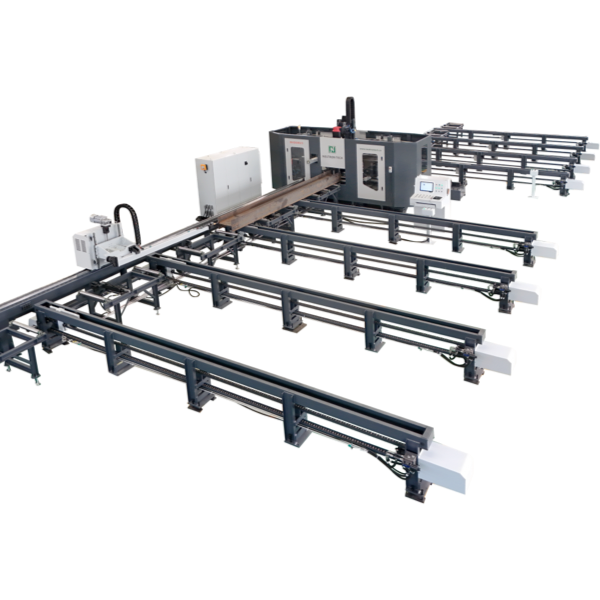
Processing heavy structural steel generates immense cutting forces. A beam drilling machine with hydraulic clamping utilizes heavy-duty vertical and horizontal hold-downs to secure the web and flanges against a fixed datum line. This robust securing mechanism neutralizes harmonic vibrations during heavy drilling operations. Vibration causes premature failure in carbide tooling. By locking the material rigidly in place, hydraulic clamping directly translates to extended tool life, perfectly cylindrical holes, and the elimination of drill bit wandering upon initial contact with the steel surface. The clamping sequence typically involves a vertical clamp descending first to flatten the web, followed by a horizontal clamp pushing the flange against the zero-reference block.
The choice of tooling dictates the required spindle specifications. Traditional High-Speed Steel (HSS) drills require lower RPMs but massive thrust force to push through structural steel. Conversely, modern carbide-tipped drills require high RPMs (often exceeding 2500 RPM) and an exceptionally rigid setup to prevent the brittle inserts from shattering. Evaluating the spindle taper, such as BT40 or CAT40, ensures compatibility with heavy-duty tool holders.
Through-Spindle Coolant Systems are mandatory for high-speed operations. Delivering a high-pressure air/oil mist or flood coolant directly through the center of the drill bit evacuates chips instantly and prevents thermal damage to the carbide inserts. Automatic Tool Changers (ATC) further enhance continuous operation. An ATC allows the machine to seamlessly swap between different drill diameters, taps, and milling cutters without any operator intervention, keeping the spindle turning and production moving.
Tooling Type | Typical RPM Range | Feed Rate Capability | Coolant Requirement | Machine Rigidity Need |
|---|---|---|---|---|
High-Speed Steel (HSS) | 200 - 600 RPM | Low to Moderate | External Flood or Mist | Moderate |
Indexable Carbide | 1500 - 3000+ RPM | Extremely High | Through-Spindle (Internal) | Maximum (Hydraulic Clamping) |
Solid Carbide | 2000 - 4000 RPM | High | Through-Spindle (Internal) | Maximum (Zero Vibration) |
Modern CNC systems feature sub-axis (X-axis) positioning. This capability allows the drill head to move longitudinally along the beam independently of the main material feeding system. Sub-axis travel, typically ranging from 200mm to 500mm, enables the machine to execute localized hole patterns, mill slotted holes, tap threads, and perform countersinking without unclamping and repositioning the entire heavy steel profile. This micro-mobility drastically reduces cycle times for complex connection details and eliminates the positioning errors associated with repeatedly moving massive structural sections back and forth through the pinch rollers.
The intelligence of the drill line resides in its CNC control and software ecosystem. The machine must possess the ability to seamlessly import DSTV (NC1) files directly from industry-standard 3D detailing software like Tekla Structures, SDS/2, or Advance Steel. This direct import eliminates manual data entry, ensuring that the hole patterns detailed by the engineer are exactly what is produced on the shop floor. The NC1 file contains all geometric data, including hole coordinates, part length, and profile type.
Beyond file parsing, evaluate the control interface for on-board diagnostics, 3D part visualization, and automated layout marking capabilities. Machines equipped with scribing or milling tools automatically mark weld locations, part numbers, and layout lines directly onto the steel. A user-friendly Human-Machine Interface (HMI) empowers operators to quickly adjust tool offsets, monitor spindle loads, and troubleshoot errors without requiring extensive G-code programming knowledge.
The physical movement of steel into and out of the machine is as critical as the drilling process itself. Assess the integration of heavy-duty infeed and outfeed roller conveyors. Cross-transfer systems are essential for moving beams laterally from staging areas onto the main conveyor line without overhead cranes. Accurate automated measurement is typically achieved through either a precision rack-and-pinion carriage system that grips the trailing end of the beam, or a sophisticated roller feed measurement system utilizing encoder wheels pressed against the steel to track its exact linear position.
Automated heavy machinery presents significant hazards on the fabrication floor. Review all essential safety integrations to ensure compliance with OSHA or CE standards. Photoelectric light curtains must guard the entry and exit points of the machine enclosure, instantly halting spindle rotation and axis movement if an operator breaks the beam. Perimeter fencing, interlocked access doors, and strategically placed emergency stop (E-stop) buttons protect personnel from automated moving parts, flying chips, and high-pressure hydraulic components.
Balancing initial equipment costs against long-term production capacity requires careful analysis. A single-spindle unit demands a lower upfront capital expenditure, making it accessible for smaller fabricators. However, a 3-spindle high-speed line offers massive production scalability. As your facility secures larger contracts and heavier tonnage requirements, the multi-spindle machine absorbs the increased workload without requiring additional shifts or overtime. The higher initial investment is offset by the permanent reduction in labor hours per ton of steel processed. Moving from a manual layout team of three workers to a single CNC operator transforms shop floor efficiency.
The physical footprint of an automated drill line extends far beyond the machine cabin. Processing a 60-foot structural beam requires a minimum of 60 feet of infeed conveyor and 60 feet of outfeed conveyor. Adding cross-transfer decks increases the required width significantly. You must analyze the hidden costs of facility reconfiguration. Moving existing equipment, reinforcing floors, or altering material flow paths to accommodate this massive linear footprint requires thorough logistical planning before finalizing any equipment selection.
Tooling consumption represents a significant ongoing operational factor. Carbide inserts carry a higher upfront cost compared to traditional HSS twist drills. However, carbide operates at significantly higher feed rates and lasts much longer before requiring replacement. HSS drills require frequent removal for resharpening, which halts production. Factoring in the longevity of carbide inserts, the efficiency of through-spindle coolant systems, and the drastic reduction in cycle times, the higher consumable cost is easily justified by the sheer volume of steel processed per shift.
Heavy structural machinery moving at rapid feed rates generates substantial dynamic loads. Inadequate flooring leads to machine settling, which destroys the precision calibration of the linear guides and measurement systems. To mitigate this risk, mandate pre-installation core drilling to verify concrete thickness and PSI ratings. Pouring dedicated, reinforced concrete pads per the manufacturer's exact specifications ensures a rigid, vibration-free foundation that maintains machine geometry over decades of heavy use.
The most advanced machine on the market will underperform if the operator lacks the necessary skills. The transition from manual layout to CNC operation exposes a significant skills gap. Mitigate this by mandating comprehensive, vendor-led, on-site training. Operators must master CNC software navigation, DSTV file manipulation, tool offset adjustments, and basic G-code interpretation. Training should focus heavily on recognizing tool wear patterns and understanding spindle load meters to prevent catastrophic tooling failures.
Unplanned downtime destroys production schedules. High-speed spindles, hydraulic clamps, and automated tool changers require strict maintenance regimens. Neglected lubrication on linear guideways or coolant system failures lead to severe mechanical damage. Implement strict daily and weekly Total Productive Maintenance (TPM) schedules. Operators must verify coolant concentration, check hydraulic fluid levels, and clear chip conveyors daily. Stocking critical wear parts, such as proximity sensors, hydraulic seals, and replacement ATC gripper fingers, ensures that minor component failures do not result in days of lost production.
Export a batch of your most complex DSTV files and send them to shortlisted vendors for accurate time studies and tooling projections.
Measure your available linear floor space, accounting for the full length of infeed and outfeed conveyors required for your longest beams.
Core drill your existing shop floor to verify concrete depth and PSI before finalizing any installation plans.
Audit your current 3D detailing software to ensure it exports clean, error-free NC1 files compatible with modern CNC controls.
A: A high-speed machine utilizes direct-drive spindles capable of high RPMs and extreme rigidity, specifically engineered to run indexable carbide tooling. Standard lines typically use lower RPM spindles designed for High-Speed Steel (HSS) twist drills, resulting in significantly slower feed rates and longer cycle times.
A: Hydraulic clamping uses high-pressure vertical and horizontal hold-downs to lock the steel profile rigidly against a fixed datum line. This eliminates harmonic vibration during cutting. Removing vibration prevents brittle carbide inserts from shattering, extending tool life and ensuring perfectly cylindrical holes.
A: Yes. Modern multi-spindle machines are equipped with sophisticated CNC controls and adaptable clamping mechanisms that accommodate a wide variety of profiles, including C-channels, L-angles, and rectangular hollow sections, provided they fall within the machine's dimensional capacities.
A: Sub-axis mobility allows the drill head to move longitudinally along the beam independently of the main material feeding system. This enables the rapid execution of closely spaced hole patterns, slotted holes, and milling operations without unclamping and repositioning the heavy steel beam.
A: The footprint depends entirely on your maximum material length. Processing a 60-foot beam requires at least 60 feet of infeed conveyor, the machine cabin footprint, and 60 feet of outfeed conveyor. Cross-transfer systems for staging material will further increase the required width.
A: Carbide tooling operates at extreme speeds, generating intense heat. Through-spindle coolant delivers a high-pressure air/oil mist or flood coolant directly through the center of the tool to the cutting edge. This instantly evacuates steel chips from the hole and prevents thermal damage to the carbide inserts.


