
Views: 0 Author: Site Editor Publish Time: 2026-09-22 Origin: Site


Investing in a new high-speed CNC line is a massive capital decision for any fabrication business. Will the system perform exactly as promised on the showroom floor? Without a strict, data-driven trial, unexpected production delays become inevitable. In this comprehensive guide, we will break down the exact step-by-step process of planning, executing, and evaluating a machine trial. You will learn how to validate speed, accuracy, and software integration to minimize lead times and maximize your return on investment.
Proper trial planning prevents costly downtime and ensures your new steel structure drilling equipment meets exact production specifications.
Pre-trial preparation involves rigorous software integration, tooling setup, and material staging.
Testing an automated system requires specific focus on tool change speed, spindle stability, and multi-axis coordination.
Integrating secondary operations during the trial ensures all-in-one processing efficiency.
A successful trial is measured by cycle time reduction, hole tolerance accuracy, and overall equipment effectiveness.
Recently, the structural steel industry has seen a massive shift toward automation to combat skilled labor shortages and rising material costs. Current industry trends reveal that fabricators are moving away from standalone, single-function machines. Instead, they demand fully integrated processing lines capable of communicating directly with 3D detailing software. Because modern fabrication relies heavily on these interconnected digital workflows, buyers are no longer accepting baseline specifications at face value. A formal machine trial is the only empirical method to verify these advanced equipment capabilities under real-world stress.
Manufacturers typically provide estimated cycle times based on highly controlled environments. A trial grounds these optimistic claims in reality. By running your specific part programs through the controller, you can accurately calculate the true return on investment. This hands-on process validates whether the machine can achieve the projected throughput required to justify the initial capital expenditure.
Integrating new heavy machinery often exposes unforeseen operational bottlenecks. A trial run acts as a stress test for your entire workflow. It highlights potential issues in material handling logistics, reveals critical gaps in operator training, and identifies workflow inefficiencies long before the machine goes into full-scale production.
Structural engineering codes demand strict adherence to dimensional tolerances. During Structural steel drilling, any micro-deviation in hole pitch or diameter can lead to disastrous assembly failures on the construction site. Consequently, trials provide the necessary documentation to prove the machine consistently meets these critical industry standards.
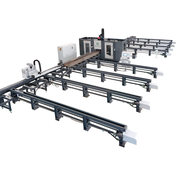
A successful trial is won during the preparation phase. Arriving at a test facility without clearly defined parameters almost always leads to inconclusive results. Engineering and production teams must establish clear performance indicators before initiating the trial. Objectives should be highly quantifiable. Practical examples include drilling 100 holes of varying diameters within a specific timeframe, achieving zero tool breakages across a specific tonnage of steel, or maintaining a precise positional tolerance across a full 12-meter beam.
Modern CNC equipment relies heavily on digital detailing. The trial must test the seamless transfer of data from the drawing board directly to the machine controller. First, technicians will import standard DSTV files or 3D models from detailing software like Tekla Structures or SDS/2. Following this, they must verify the post-processor. This crucial step confirms that the software translates hole coordinates, diameters, and material profiles without requiring dangerous manual data entry.
The physical environment must support high-precision machining. Preparations go beyond simply plugging the machine in. Specifically, technicians must check the stability of the 3-phase power supply to prevent sudden controller resets. In addition, they verify hydraulic fluid levels for robust clamping systems, ensure consistent pneumatic pressure, and confirm the precise leveling of the machine bed on the concrete foundation to prevent geometric distortion during heavy operations.
Testing a machine on thin, easily machinable materials you rarely process provides little practical value. The trial must reflect your daily operational reality on the shop floor. It is highly recommended to use representative materials that mirror your standard workload. Testing should occur across varying thicknesses and material grades, such as standard A36 or high-strength A992.
Material Profile | Typical Dimensions | Trial Focus Area | Recommended Machine Spec |
|---|---|---|---|
Heavy H-Beams | Web up to 1000mm | Hydraulic clamping stability, deep hole chip evacuation | Heavy-duty 3-axis independent spindle control |
Medium I-Beams | Web up to 500mm | Flange and web drilling synchronization | High-RPM spindle with rapid feed capabilities |
U-Channels & Angles | Asymmetrical profiles | Vibration control and rigid clamping | Automated adaptive hydraulic clamping systems |
High-speed drilling requires high-performance tooling. The trial should utilize the exact tooling you plan to use in production. Whether that involves solid carbide drills, indexable insert drills, or specialized high-speed steel tools, the setup must be authentic. Furthermore, verifying the pressure and flow of through-tool coolant is critical. Proper coolant application directly impacts chip evacuation and tool life during aggressive cutting cycles.
With preparations complete, the physical testing begins. This phase moves from simulated, quiet runs to aggressive, loud metal removal. Before any steel is cut, operators execute a dry run. The CNC program runs without material loaded in the machine. This allows technicians to visually verify tool paths, confirm safe clearance heights, and ensure smooth, synchronized movements across all axes. Ultimately, it is a critical safety step to prevent catastrophic spindle crashes.
When evaluating a beam drilling machine with ATC, the focus shifts to mechanical reliability and speed. The trial must evaluate the automatic tool changer's ability to seamlessly swap between different drill diameters, taps, and countersinks without human intervention. Technicians listen for the crisp clatter of the pneumatic grippers and verify that the spindle sensors accurately confirm tool seating before the next cycle begins.
The live cutting test is the core of the trial. Operators execute the first live drills into the steel. During this phase, technicians closely monitor spindle load meters, listen for excessive vibration, and observe the shape and color of the chips forming. The goal is to dial in the optimal rotation speed and feed rates. Finding this precise balance ensures maximum production speed without compromising the lifespan of expensive carbide consumables.
When validating a complex CNC system, evaluating the primary spindle is only one part of the equation. Modern fabrication facilities rely on interconnected systems to maintain a continuous flow of materials.
Traceability and assembly accuracy are critical in modern steel fabrication. Therefore, testing the synchronization between the primary drilling unit and the beam marking machine is a mandatory step. Whether the machine utilizes hard stamping, carbide scribing, or plasma layout marking, the trial must verify that the CNC controller accurately calculates the mechanical offset. During the trial run, operators program a test piece requiring both part numbers and weld layout lines. After the sequence is completed, quality control personnel measure the distance from the drilled holes to the scribed layout lines to ensure exact alignment for downstream welders.
The most efficient spindle in the world cannot compensate for a bottleneck in material handling. During this phase, the trial evaluates the infeed and outfeed roller conveyors, cross-transfer mechanisms, and hydraulic clamping systems. Operators will load the heaviest and longest beams specified in the machine capacity chart to test the torque of the drive rollers. Any slippage or micro-movement during the high-speed drilling cycle will result in out-of-tolerance holes or shattered drill bits.
Once the live cutting tests are complete, the trial moves into the objective evaluation phase. This step relies entirely on empirical data, precise measurements, and standardized quality control protocols.
The primary objective is to produce connections that align perfectly during field erection. Quality assurance technicians utilize calibrated instruments, including digital calipers and micrometers, to verify the output against the original CAD files. They check for oversized holes caused by spindle runout, verify the pitch between hole groups, and ensure the drill entered perfectly perpendicular to the material surface.
To quantify the investment, engineers conduct a strict cycle time analysis. This is calculated from the moment the material enters the machine to the moment it is discharged. This data is then compared against the facility's existing methods. For example, if a traditional manual layout takes 45 minutes to process a complex column, and the trial machine completes it in 8 minutes, the empirical time savings can be directly plugged into return on investment calculations.
High-speed drilling generates immense heat and friction. After the trial runs, technicians meticulously inspect the interior surface of the drilled holes. They should be smooth, with clean entry and exit points free of heavy burrs. Simultaneously, the drill bits are examined under magnification to spot signs of premature wear, such as micro-chipping on the cutting edge or thermal discoloration.
Even with meticulous preparation, mechanical and software anomalies can occur when running a machine under live loads for the first time. Identifying these challenges during the trial is precisely why they are conducted.
A frequent challenge occurs when the machine CNC controller fails to read the imported DSTV file correctly, resulting in missing holes or mirrored coordinates. This is typically a post-processor mapping issue. Software engineers resolve this by analyzing the raw G-code text file and adjusting the post-processor settings to ensure data fields map correctly to the machine specific logic.
During the live cutting test, the machine might emit a high-pitched squealing noise, resulting in a rough hole finish. Chatter is usually a symptom of inadequate rigidity or incorrect cutting parameters. Technicians will first verify hydraulic clamping pressure. If the material is secure, they will tweak the feed and speed overrides to find a more stable cutting frequency.
When drilling through thick structural flanges, metal chips may fail to break, forming long stringy nests that wrap around the tool holder. Effective chip evacuation relies on optimizing the through-tool coolant pressure to flush chips upward. Alternatively, the CNC program can be modified to utilize a peck drilling cycle, which retracts the drill slightly to forcefully break the chips.
The successful completion of the physical trial marks the beginning of the integration phase. Transitioning from a testing environment into daily production requires structured documentation and operator empowerment.
A machine is only as capable as the personnel operating it. The trial phase should never be conducted exclusively by the manufacturer technicians. Your operators must be heavily involved in on-the-job training, covering essential daily tasks like navigating the CNC interface, setting tool length offsets, and recovering from emergency stops.
The formal conclusion is the Factory Acceptance Test sign-off. This binding document confirms that the equipment has met all predetermined performance indicators, including verified cycle times and dimensional tolerance reports. Only after this document is signed does the equipment officially shift into active production status.
Observations made during the trial serve as the foundation for the machine preventative maintenance schedule. Based on runtime data, maintenance managers will schedule daily tasks like checking fluid levels, weekly tasks like greasing linear guideways, and monthly tasks like calibrating axis encoders to protect the capital investment.
A well-planned trial ensures your machine achieves true profitability. Rigorous testing eliminates guesswork in your daily operations, allowing fabricators to evaluate software, tooling, and material handling under real-world conditions. This meticulous process bridges the gap between a showroom purchase and high-efficiency production. If you are ready to upgrade your fabrication line, contact the engineering team at NeutronCM to schedule your custom trial. Explore our specific range of robust, automated drilling equipment tailored to meet your exact production demands today.
A typical machine trial requires between 1 to 3 days to complete thoroughly. The exact duration depends heavily on the complexity of the equipment. A standard single-spindle machine may only require a single day for basic calibration and live cutting. However, a multi-spindle machine equipped with automated tool changers and complex cross-transfer material handling will require multiple days to test all software integrations and tool sequences under various load conditions.
While equipment manufacturers maintain standard carbon steel stock for baseline testing, it is highly recommended that you provide your own specific materials. Sending your exact structural profiles along with your actual CAD files ensures that the machine is calibrated for your unique production environment. Testing on your own material eliminates variables related to material hardness and specific engineering tolerances.
Yes. Modern CNC beam drilling centers are designed as multi-functional processing units. If the machine is equipped with an automatic tool changer and a spindle capable of rigid tapping or helical milling, these functions must be tested during the trial. Operators will evaluate the machine ability to seamlessly swap from a through-hole drill to a tapping tool, verifying thread quality without manual intervention.
A marking unit is integrated directly into the primary CNC program. The detailing software generates a single file that contains both hole coordinates and marking instructions. During the process, the CNC controller directs the beam to the marking unit either immediately before or after the drilling sequence, significantly reducing overall lead times by eliminating a separate manual workstation.
If empirical data shows the machine is falling short of guaranteed cycle times, a structured troubleshooting loop is initiated. Manufacturer technicians will analyze the process to identify bottlenecks. Solutions may include optimizing the CNC program to reduce unnecessary rapid traverse movements, adjusting feeds and spindle speeds, or modifying the geometry of the cutting tools until the equipment consistently meets the agreed-upon performance indicators.
During a formal trial, engineers must document several critical metrics to ensure compliance. These include spindle motor load percentages during maximum feed rates, exact tool change times, dimensional accuracy of the drilled holes against the 3D model, and the total cycle time from material infeed to outfeed. Documenting these metrics provides a clear baseline for future maintenance and production planning.
Environmental factors play a significant role in high-precision machining. Temperature fluctuations can cause thermal expansion in both the machine frame and the steel profiles, leading to micro-deviations in hole pitch. Additionally, unstable power grids or inadequate compressed air supply can trigger controller faults or slow down pneumatic clamping systems. Ensuring a stable, climate-controlled testing environment is vital for accurate trial results.


