
Views: 0 Author: Site Editor Publish Time: 2026-10-13 Origin: Site


Procuring industrial machinery is a heavy capital investment. A vague specification or an incomplete blueprint often leads to hidden costs and painful delays. Purchasing industrial equipment requires strict alignment between your facility engineering requirements and the manufacturer capabilities. Securing an accurate, bottom-line price starts with the data you provide.
In this technical guide, we break down exactly which engineering drawings, CAD files, and machining specifications guarantee precise pricing. You will learn how to structure your blueprint package to ensure your next procurement cycle runs smoothly. This approach prevents budget overruns and eliminates unexpected post-purchase modifications.
Clarity Equals Accuracy: Comprehensive part and assembly drawings ensure your equipment quote is exact. This avoids unexpected customization fees or last-minute structural modifications.
Digital Formats Dominate: Modern equipment manufacturers rely on digital CAD and CAM files like DXF, DWG, and STEP alongside traditional 2D blueprints to simulate production runs.
Tolerances Dictate Price: Machining specifications and drawing notes directly influence the required spindle power, frame rigidity, and overall machine cost. Hole tolerances and surface finishes are especially critical.
Facility Layout Matters: Layout drawings verify that the machine physically fits your floor plan. This is vital when incorporating hydraulic clamps, chip conveyors, and automated material handling systems.
Buying heavy industrial equipment is a major capital expense. You need strict alignment between shop floor reality and the purchasing budget. Blueprints serve as the critical bridge translating operational demands into manufacturing realities. When a buyer requests a quote for a High speed plate drilling machine, the engineering team meticulously analyzes the provided drawings. They determine the exact mechanical, electrical, and hydraulic specifications required to perform the job efficiently.
Missing vital information forces manufacturers to make assumptions. If maximum material hardness or specific geometric tolerances are absent, suppliers apply buffer pricing to protect themselves. They might quote a higher-tier spindle motor, a heavier stress-relieved cast-iron frame, or unnecessary software add-ons. Providing complete engineering drawings upfront eliminates these ambiguities. Buyers then pay only for the exact capabilities they need.
Engineering drawings also help manufacturers determine if a standard off-the-shelf machine model will suffice. Standard models are engineered to handle typical structural steel processing tasks. They offer an excellent balance of performance and cost-efficiency.
Unique challenges reveal themselves in detailed blueprints. Exceptionally thick steel plates, non-standard hole patterns, or the need to drill multiple stacked plates simultaneously demand customization. Drawings allow the supplier to identify if custom hydraulic clamping fixtures, expanded worktables, or specialized gantry heights are necessary. Without these technical documents, a buyer might receive a quote for a standard machine. They would only discover during shop floor commissioning that the equipment cannot physically accommodate their specific parts.
The structural steel fabrication industry is experiencing a massive shift toward automated, data-driven quoting. Forward-thinking manufacturers are moving away from manual blueprint interpretation. Instead, they are adopting Model-Based Definition workflows. This trend means that the 3D CAD model itself contains all manufacturing data, including geometric tolerances and material specifications.
By leveraging digital twins and automated quoting algorithms, application engineers can run virtual simulations of the drilling process before a single piece of metal is cut. This technological shift drastically reduces quoting lead times and eliminates human error. As global supply chains tighten, providing comprehensive digital models ensures your project is evaluated faster and with pinpoint accuracy. Facilities that adapt to this digital-first submission process consistently secure more competitive and reliable equipment pricing.
Despite the rapid rise of 3D modeling, traditional 2D part drawings remain the foundational document for quoting industrial machinery. These blueprints, known as orthographic projections, provide a clear two-dimensional view of the workpiece from multiple angles. They typically showcase the top, front, and side views.
Machine manufacturers look for three primary data points when reviewing 2D blueprints. Maximum plate thickness dictates the required Z-axis stroke and the type of drill bits the machine must support. The range of hole diameters directly influences the spindle torque and RPM capabilities. The complexity of the drilling pattern helps the manufacturer determine the necessary rapid traverse speeds of the X and Y axes to ensure optimal cycle times.
Part drawings show individual components, while assembly drawings illustrate how those parts fit together in the final product. Providing these comprehensive drawings helps the machine manufacturer understand the end-use context of the processed steel plates.
Plates used in bridge building or wind tower construction face strict regulatory standards regarding structural integrity and fatigue resistance. This context informs the manufacturer that the machine must produce highly precise, burr-free holes to prevent stress fractures. If the assembly drawings indicate the plates are for basic low-stress frameworks, the manufacturer can quote a more standard, economical machine configuration.
The drawing notes and machining specifications are the most critical yet frequently overlooked sections of an engineering blueprint. These text blocks contain vital empirical data that cannot be easily represented by lines and dimensions. Material grades are a primary focus. A drawing note specifying standard carbon steel like A36 will result in a vastly different machine quote than a note specifying high-strength alloy steel, Hardox, or stainless steel.
Harder materials generate immense heat and cutting resistance. They require a machine equipped with higher torque servo motors, rigid box-way guides, and potentially through-spindle coolant systems.
Material Grade Specification | Typical Hardness Brinell Scale | Impact on Machine Quote Requirements |
|---|---|---|
Carbon Steel ASTM A36 | 119 - 159 HBW | Standard spindle torque; external coolant sufficient. |
High-Strength Low-Alloy | 180 - 230 HBW | Increased spindle torque; rigid gantry structure. |
Stainless Steel 304/316 | 160 - 200 HBW | Lower RPM, high torque; through-spindle coolant required. |
Wear-Resistant Hardox 400 | 370 - 430 HBW | Maximum spindle power; heavy-duty vibration damping. |
Modern manufacturing has transitioned from manual interpretation to digital execution. A contemporary machine operates using digital inputs interpreted by its Computer Numerical Control system. Providing digital Computer-Aided Design files during the quoting phase is no longer just a convenience. It is an absolute necessity for accurate pricing.
Top-tier manufacturers utilize automated quoting algorithms that ingest these CAD files to run virtual simulations of the drilling process. Application engineers simulate tool paths to calculate exact cycle times and evaluate tool wear rates. They also verify that the machine axes have sufficient travel distance. This empirical data ensures the quoted machine will meet the buyer production volume without relying on guesswork.
Providing digital files in universally accepted formats facilitates a smooth quoting process. Different file types serve distinct purposes in the evaluation stage. DXF and DWG are the industry-standard formats for 2D vector graphics. They are highly efficient for representing flat plate layouts, hole coordinates, and basic geometric profiles. CNC nesting software reads these files to optimize material yield.
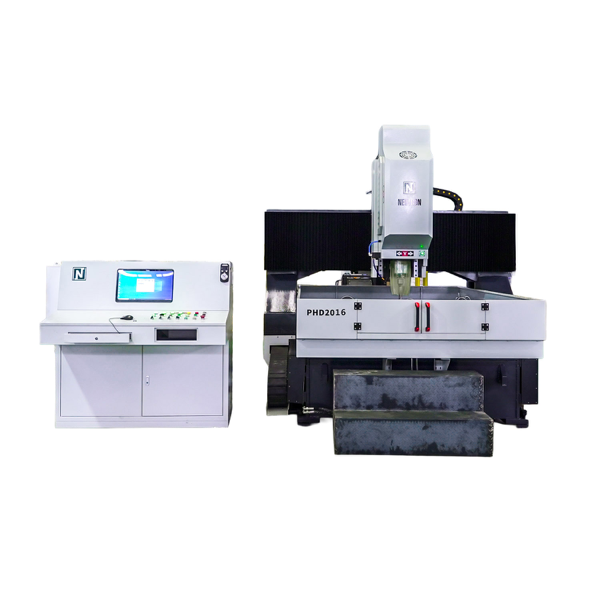
STEP and IGES formats are used for 3D modeling. A flat steel plate might seem inherently 2D, but 3D STEP files are invaluable when the part requires complex multi-process machining. This includes counterboring, tapping, or light milling along the edges. When evaluating a CNC High Speed Plate Drilling Machine, providing a comprehensive STEP file allows the engineering team to verify exact capabilities. For instance, they can confirm if a model like the PHD2016, with its high-speed spindle reaching up to 3000 RPM and processing thickness capacity of 100mm, can seamlessly accommodate the specific multi-depth requirements of your workpiece.
Geometric Dimensioning and Tolerancing is a standardized system used on engineering drawings to communicate the allowable variation in part geometry. The strictness of these symbols on your blueprints has a direct, proportionate impact on the quoted machine price.
Extremely tight true-position tolerances for hole locations require the manufacturer to quote a system built for absolute precision. This typically means upgrading the machine frame to a heavier, stress-relieved cast iron structure to minimize thermal expansion. It also necessitates premium-grade linear guide rails, high-precision ball screws, and closed-loop optical scale feedback systems. Standard structural tolerances allow for the quotation of more economical mechanical components.
Specific hole dimensions and thread specifications dictate the type of spindle technology the machine must possess. The spindle is one of the most expensive variables in a quote.
Large diameter holes require a spindle capable of delivering massive low-end torque. This pushes the drill bit through thick steel without stalling. Smaller diameter holes require high-speed spindles often exceeding 3,000 RPM to achieve the correct surface speed for the cutting tool. If the blueprint notes require deep-hole drilling where the depth exceeds three times the diameter, the manufacturer must quote an internal through-spindle coolant system. This evacuates chips and prevents catastrophic tool breakage.
Dimensions, thickness, and flatness tolerances specified on your drawings dictate the required workholding solutions. High-speed drilling generates immense downward and rotational cutting forces. A steel plate that is not secured properly will vibrate. This leads to shattered drill bits, out-of-tolerance holes, and poor surface finishes.
Standard mechanical clamps will not suffice if your blueprints indicate processing relatively thin plates or stacking multiple plates for simultaneous drilling. In these scenarios, engineers must quote a CNC Plate Drilling Machine equipped with advanced hydraulic clamping systems. Models like the PLD2016 utilize robust hydraulic clamping blocks that apply consistent, high-pressure force across the workpiece. This prevents micro-vibrations and ensures structural integrity throughout the machining cycle.
Obtaining an accurate quote is equally about physical integration into your existing manufacturing environment. A heavy-duty machine is a substantial piece of capital equipment requiring significant floor space. The physical footprint extends far beyond the main machine bed and the moving gantry.
Engineers review your facility layout looking for spatial constraints that might necessitate a custom machine build. The total quoted footprint must account for external electrical cabinets, hydraulic power units, automated chip conveyors, and high-capacity coolant filtration tanks. Maintenance personnel also need adequate clearance around the perimeter to perform routine inspections safely. Structural pillars, narrow aisles, or low ceilings may require the manufacturer to quote a customized compact version of the equipment. They might need to reroute cable drag chains or alter the position of the hydraulic station.
Industrial steel plates are massive and heavy. The logistics of moving them onto and off the machine are critical to production efficiency. Your facility layout drawings should indicate exactly how the machine will be fed.
Plates can be loaded via an overhead gantry crane, a heavy-duty forklift, or an automated roller conveyor system. If your layout relies on inline roller conveyors, the machine manufacturer must quote a system with compatible infeed and outfeed table heights. They may also need to include automated datum-pushers and hydraulic lifting rollers in the quote. This facilitates seamless material workflow and prevents bottlenecks in your production line.
Omission of exact material specifications is a frequent error that delays the quoting process. Simply writing Steel or Mild Steel on a blueprint is entirely insufficient for modern CNC machining quotes.
Manufacturers need to know the specific grade and hardness measured in Brinell HBW or Rockwell HRC. Failing to specify the exact hardness leads to two negative outcomes. The manufacturer either quotes an underpowered machine that stalls during production, or they quote an unnecessarily powerful, expensive machine to cover their liability. Precise material data ensures precise motor sizing.
Drafting circles on a 2D plane without providing section views or drawing notes is a dangerous oversight. Engineering drawings must clearly define hole depth and finishing requirements. They must differentiate between through-holes which pass entirely through the plate, blind holes which stop at a specific depth, and tapped holes which require internal threading.
Mixing up these requirements skews the quote significantly. If a drawing fails to indicate that certain holes require threading, the manufacturer will not include the necessary tapping software macros. They will also omit specialized tapping chucks or the specific spindle encoder required for rigid tapping operations.
Buyers often submit blueprints of their most complex individual parts but fail to state the maximum dimensions of the raw steel plates. The quote must account for the maximum length, width, and weight of the raw material.
Imagine a scenario where a buyer plans to load a 10,000 kg steel plate, but the submitted drawings only show a small 50 kg finished part. The manufacturer will quote a standard worktable. When that massive plate is eventually loaded onto the shop floor, it could permanently warp the machine bed or overload the linear guideways.
Do not simply send blueprints of your easiest parts. Select a portfolio of worst-case scenario parts to ensure the quoted equipment can handle your entire production portfolio. Gather drawings that feature the thickest plates, the hardest material grades, the tightest tolerances, and the most complex multi-diameter hole patterns. If the quoted machine can process your most difficult parts efficiently, it will handle standard production with ease.
Create a comprehensive and organized technical package. Relying solely on a scanned PDF blueprint is no longer standard practice. Include high-resolution PDF copies of all 2D blueprints clearly showing all drawing notes. Include the corresponding digital CAD files alongside the PDFs. Finally, attach a facility layout drawing indicating where the machine will be installed and how material will flow through the area.
Treat the drawing submission as a formal technical handover rather than a simple transactional email. Request a pre-quote consultative meeting with the machine manufacturer engineering team.
Review the drawings together, clarify any ambiguous notes, and discuss your long-term production goals. The manufacturer may offer Design for Manufacturing suggestions. Pointing out minor adjustments to your blueprints could allow you to use a standard machine model rather than requiring an expensive custom build. This consultative approach ensures the final quote aligns perfectly with your technical requirements and your capital budget.
Accurate quotes rely entirely on clear and comprehensive engineering drawings. Providing detailed 2D blueprints, 3D CAD files, and precise facility layouts empowers the manufacturer to configure a machine perfectly matched to your operational needs. This diligence prevents hidden costs, eliminates unexpected production delays, and ensures you get the right equipment the first time. Gather your most complex part drawings today. We highly recommend visiting neutroncm.com to explore standard and custom machine models, and initiate a technical consultation with their engineering team to guarantee a precise, tailored quote for your shop floor.
While 3D models like STEP files are highly helpful for visualizing complex components and multi-axis operations, standard 2D drawings in DXF or DWG formats are usually sufficient for an accurate quote. These 2D files clearly show hole layouts, overall plate dimensions, and material specifications, providing the core empirical data manufacturers need.
Different materials require distinct cutting forces and tooling approaches. Harder steel plates demand a machine equipped with higher spindle torque, a more rigid machine frame, and internal cooling systems to maintain tool life. Omitting the exact material grades can lead to quoting an underpowered machine or inflating the price unnecessarily to cover potential risks.
The most frequent error is omitting the maximum plate weight and geometric tolerances. Without this critical data, machine manufacturers cannot accurately recommend the appropriate worktable load capacity, the necessary hydraulic clamping force, or the specific spindle power required to handle your largest raw materials.
Yes. Once the technical specifications are finalized and the quote is agreed upon, a reputable manufacturer will supply detailed foundation and layout blueprints. This allows your facility managers to prepare the shop floor, route electrical wiring, and pour necessary concrete foundations prior to the equipment arrival.
Modern computer numerical control systems feature advanced software capable of importing DXF and DWG files directly. The system automatically converts your digital drawings into precise machining programs. This significantly reduces manual data entry errors and accelerates the overall production setup process on the shop floor.
Extremely tight geometric tolerances often require custom engineering, heavier cast-iron frames, and specialized procurement for high-precision ball screws or optical scales. These custom requirements can extend the manufacturing and assembly lead times compared to standard off-the-shelf models built for normal structural tolerances.
A 2D DXF file is excellent for flat plate profiling and basic hole coordinates, which is sufficient for standard drilling. A 3D STEP file provides volumetric data, allowing engineers to simulate multi-depth processes like counterboring, tapping, and edge milling. 3D files offer a more comprehensive view, ensuring the quoted machine spindle stroke and automatic tool changer can handle complex operations without collision.


