
Views: 0 Author: Site Editor Publish Time: 2026-10-06 Origin: Site


Connection plates serve as the critical nodes in structural steel fabrication. They are the essential components holding bridges, commercial skyscrapers, and heavy industrial infrastructure together. Gusset plates, splice plates, and base plates bear immense load transfers daily. Therefore, the precision of the bolt holes within these heavy metal pieces is non-negotiable. A microscopic deviation of just a fraction of a millimeter can halt an entire construction project. When bolt holes fail to align on-site, erection crews face severe delays, expensive rework, and compromised structural integrity.
Historically, shop floors relied on traditional manual drilling methods, radial arm drills, or mechanical punch presses. These legacy systems simply cannot keep pace with the high-volume and high-precision demands of modern infrastructure projects. Setup times drag on for hours, and material handling remains incredibly clunky. Moreover, relying on manual layout introduces a massive margin for human error. To resolve these operational bottlenecks, implementing a CNC High Speed Plate Drilling Machine has become the definitive solution for rapid and accurate hole making. By fully automating the positioning and cutting processes, fabricators achieve exceptionally strict tolerances on every single batch. This guide walks workshop managers, machine operators, and production engineers through the exact setup process, tooling synergy, software integration, and equipment selection required to maximize production efficiency.
Precision is Paramount: Meticulous calibration of automated drilling systems eliminates hole deviation, ensuring seamless on-site assembly and zero rework.
Workholding Matters: Advanced hydraulic clamping systems drastically reduce material vibration, prevent micro-movements, and cut down batch setup times.
Tooling Synergy: Combining drilling, boring, and reaming operations within a single programmed setup maximizes hole quality and extends expensive tool life.
Software Integration: Linking CAD and CAM detailing software directly to your equipment streamlines material flow and minimizes human data-entry errors.
Choosing the Right Equipment: Selecting machines engineered for high-velocity operation yields an immediate return on investment by radically increasing throughput.
The structural steel sector is currently undergoing a massive shift toward automation and digital integration. Driven by chronic shortages in skilled manual labor and fluctuating raw material costs, forward-thinking fabricators are moving away from isolated manual workstations. Instead, the industry is rapidly adopting interconnected systems capable of directly reading 3D detailing models from structural engineers. The push for zero-rework prefabrication means that components must arrive on the job site ready for immediate bolt assembly. This industry-wide evolution underscores exactly why legacy equipment is being phased out. Modern fabrication floors now demand intelligent machinery that self-calibrates, processes complex nesting algorithms, and completely removes manual layout variability from the production equation.
Structural steel connection plates are engineered to exact specifications. When erecting a steel framework, massive beams and columns are joined using high-strength friction-grip bolts that pass through these plates. Standard structural codes dictate that bolt hole alignment must be accurate to within plus or minus 1.5 millimeters across large structural spans. Meanwhile, individual hole diameters must not deviate by more than plus or minus 0.2 millimeters. Meeting these strict tolerances guarantees proper bolt tensioning and overall structural rigidity.
In traditional machining environments, operators constantly face a direct trade-off between speed and accuracy. Pushing a manual drill too fast inevitably results in tool deflection, oversized holes, and rapid tool wear. In contrast, a modern High-speed plate drilling machine is structurally designed to bridge this gap seamlessly. Utilizing heavy-duty gantry structures, high-torque servo motors, and rigid linear guideways, these systems feed solid carbide drill bits through thick steel plates at exceptional rates.
To illustrate the operational differences, consider the stark contrast between traditional methods and modern automated systems. While a radial arm drill relies on manual center punching and tops out around 1,500 RPM, advanced CNC systems operate upwards of 3,000 RPM with automated positioning. Equipment like the PHD series utilizes robust BT40 or BT50 spindles to deliver massive torque directly to the cutting edge. This technological leap slashes the average cycle time per hole from roughly a minute down to mere seconds.
Transitioning to advanced drilling technology directly influences a workshop's profitability. Connection plates account for a massive volume of the total pieces processed in a typical fabrication shop. By significantly reducing cycle times, fabricators can process hundreds of plates per shift rather than dozens. When extrapolated across thousands of holes in a standard infrastructure project, the labor hours saved are monumental. Furthermore, the sheer reduction in scrap material and the total elimination of on-site rework mean that operational overhead per unit plummets. This efficiency allows fabricators to bid much more competitively on large-scale contracts.
Operational Metric | Traditional Radial/Manual Drill | High-Speed CNC Drilling Machine |
|---|---|---|
Setup & Layout Time | High manual marking required | Zero manual layout via CAD integration |
Cycle Time per Hole | 45 to 60 seconds | 5 to 10 seconds |
Positional Accuracy | Prone to human error and drift | Absolute precision within 0.1 mm |
Tool Cooling System | External flood coolant | Internal through-spindle high pressure |
Workholding | Manual clamps prone to vibration | Automated hydraulic clamping arrays |
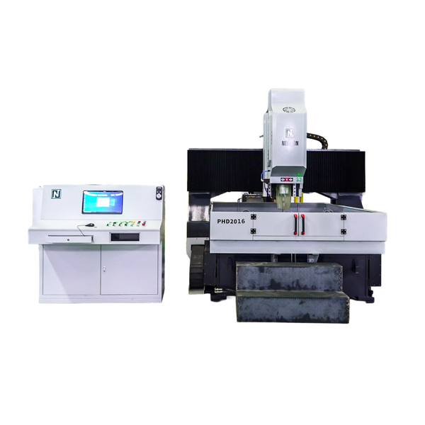
Before any cutting tool touches the steel, a rigorous pre-setup routine must be established on the shop floor. Skipping these foundational steps often leads to catastrophic tool failures, scrapped materials, or severe mechanical damage to the spindle.
The condition of the raw steel plate directly dictates the success of the drilling process. Before loading materials onto the machine bed, operators must conduct a thorough physical inspection. Assess the plate for flatness first. A severely warped plate will not sit flush on the machining bed. This uneven surface causes the drill bit to enter the material at an angle, leading to dangerous tool deflection and immediate insert failure.
Next, operators should run a gloved hand along the flame or plasma-cut edges to check for hardened slag. Thick mill scale or leftover slag acts as a severe abrasive that can instantly shatter a carbide insert. Finally, thickness consistency must be verified with calipers. If a plate is significantly thicker than the programmed parameters, the rapid-approach sequence of the tool might violently crash into the material before switching to the slower cutting feed rate.
Automated drilling systems are only as accurate as their baseline calibration. Before initiating a production run, the operator must verify the geometric alignment of the machine. This sequence begins with homing the machine, ensuring the gantry X-axis, spindle head Y-axis, and spindle feed Z-axis return to their absolute mechanical zero positions.
Specifically, engineers recommend measuring spindle runout using a precision dial indicator. Runout refers to the microscopic wobble of the tool holder as it rotates. For high-speed carbide drilling, this metric must typically be kept below 0.02 millimeters. Additionally, it is vital to wipe down the physical datum blocks. Even a tiny metal chip lodged against a datum block can throw the starting coordinates off by several millimeters, rendering the finished connection plate useless.
Operating heavy CNC machinery involves massive kinetic energy and immense material weights. Strict safety protocols are non-negotiable. Operators must ensure that overhead cranes, magnetic lifters, or vacuum hoists are properly rated for the load and functioning smoothly. Machine safety interlocks, light curtains, and emergency stop buttons require daily testing. Lock-out tag-out procedures must be strictly enforced during any maintenance or manual tool-changing process to prevent accidental spindle activation.
With the pre-setup checklist complete, shop floor personnel can transition into the actual production setup. This phase seamlessly integrates material handling, workholding, cutting tools, and digital software to maximize throughput.
Efficiency begins long before the spindle starts turning. Moving heavy steel connection plates onto the machine bed must be a highly orchestrated process. Modern fabrication shops utilize integrated roller conveyors, automated cross-transfers, and heavy-duty electromagnets to position raw plates smoothly. The operator lowers the plate gently, hovering just millimeters above the surface to avoid gouging the bed. The material is then pushed firmly against the pre-calibrated datum stops, establishing a precise physical origin point that perfectly matches the digital model.
Once the material is precisely positioned, it must be secured immovably. High-speed drilling generates immense rotational forces and a violent upward pull when the drill bit breaks through the bottom of the steel. Standard mechanical clamps are often insufficient and labor-intensive. Implementing an advanced CNC Plate Drilling Machine equipped with automated hydraulic clamping arrays is critical here. These clamps apply uniform, high-pressure downward force across the plate in a matter of seconds. This rigid setup completely absorbs micro-vibrations and harmonic chatter during the cutting cycle, ensuring perfectly cylindrical holes and dramatically extending the lifespan of expensive carbide inserts.
High-velocity machining requires highly specific tooling strategies. Unlike older High-Speed Steel drills, modern setups utilize solid carbide or indexable insert drills capable of withstanding massive heat and friction. Creating the perfect connection plate often requires a synergy of operations loaded into the Automatic Tool Changer:
Drilling: The aggressive primary operation used to remove the bulk of the steel rapidly.
Boring: Deployed to open a drilled hole to a non-standard diameter or correct slight positional deviations.
Reaming: Applied when the inner hole requires an exceptionally smooth surface finish for specialized friction-grip bolts.
Operators must meticulously measure tool length offsets and input them into the controller. Verifying the flow of high-pressure, through-spindle coolant is equally mandatory. This fluid evacuates metal chips from deep holes and prevents catastrophic thermal shock to the cutting edge.
The final crucial step before pressing cycle start is digital integration. Today's steel fabrication relies on a seamless flow of data from the structural engineering department directly to the shop floor. Detailing software generates standardized files containing exact geometric data, hole sizes, and coordinates for every single connection plate.
Instead of manually keying coordinates into an interface, operators import these files directly into the CAM software of the machine. The system automatically nests the parts to maximize raw material yield and generates the necessary machining code. By reviewing the 3D simulation on the controller screen, the operator can visually verify that no hydraulic clamps sit in the cutting path and that tool changes occur logically. This completely eliminates human error and prevents expensive machine crashes.
Purchasing the right automated drilling equipment is a major capital investment. To ensure a rapid return on investment, workshop managers must evaluate machines based on specific operational capabilities rather than just price. When selecting a machine for connection plates, look for these critical specifications:
Spindle Power and Speed: Look for a robust BT40 or BT50 spindle capable of reaching at least 3,000 RPM. High torque at lower speeds is necessary for large diameter holes, while high RPM is crucial for carbide tooling efficiency.
Maximum Drilling Diameter: Ensure the machine can handle hole diameters up to 50 millimeters to accommodate heavy industrial base plates and splice plates.
Clamping Mechanism: Insist on automated hydraulic clamping arrays. Manual clamping simply cannot suppress the harmonic chatter generated by high-speed carbide drills.
Coolant Delivery: Internal through-spindle coolant is an absolute necessity. External flood coolant cannot clear chips effectively from deep holes in thick steel plates.
Software Compatibility: The machine controller must seamlessly accept standard detailing files like DSTV and DXF without requiring complex third-party conversion software.
A single hole misalignment can halt an entire erection crew. Therefore, meticulous machine setup guarantees perfect bolt holes every time, effectively preventing catastrophic on-site delays. Utilizing advanced automated equipment fundamentally improves daily workshop output and profit margins. By strictly adhering to pre-setup checklists, leveraging hydraulic clamping to kill vibration, and integrating seamless CAD software, steel fabricators can transform connection plate production from a notorious bottleneck into a highly streamlined, profitable operation. Upgrade your fabrication floor today by selecting machinery engineered for uncompromising precision.
Ready to eliminate production bottlenecks and double your connection plate throughput? Evaluate your current cycle times and explore the advanced specifications of Neutron's high-speed drilling solutions at Neutroncm.com to find the exact machine configuration that matches your fabrication needs.
Hydraulic clamping applies consistent, uniform downward pressure across the steel plate, which manual clamping cannot guarantee. This rigid hold eliminates micro-vibrations and harmonic chatter during high-speed drilling. Reducing vibration not only ensures the hole remains perfectly cylindrical and within strict tolerances, but it also prevents the premature chipping and shattering of expensive carbide cutting tools.
Through-spindle coolant pumps high-pressure fluid directly down the center of the drill bit, exiting right at the cutting edge. This serves two vital purposes. First, it instantly cools the tool and the material to prevent thermal distortion. Second, it forcefully flushes metal chips up and out of the hole. Without it, chips pack at the bottom of a deep hole, causing the drill bit to bind, overheat, and eventually snap.
Deutscher Stahlbau-Verband files, commonly known as DSTV, are the industry-standard digital format used in structural steel detailing. They contain the exact 3D geometric data of a part, including plate dimensions, hole locations, and diameters. Importing these files directly into the software of the machine eliminates the need for manual data entry and physical layout marking. This drastically reduces setup time and virtually eliminates human programming errors.
The ideal spindle speed depends entirely on the type of tooling and the hole diameter. Traditional High-Speed Steel drills typically operate under 1,000 RPM to prevent burning up. However, modern solid carbide or indexable insert drills perform optimally between 2,000 and 3,000 RPM. Running carbide tools too slowly actually increases cutting resistance and leads to premature insert failure.
Preventing tool deflection requires a combination of rigid workholding, proper tool length, and material preparation. First, ensure the steel plate is perfectly flat and clamped hydraulically so it cannot flex. Second, use the shortest possible drill bit to minimize leverage forces. Finally, verify that the spindle runout is calibrated correctly and that the drill bit is not entering the material on a severe angle caused by warped steel.
Basic machine homing and datum block cleaning should be performed daily or at the start of every shift. Checking spindle runout with a dial indicator and verifying gantry squareness should be part of a routine weekly or bi-weekly preventative maintenance schedule. These checks must also be performed immediately after any accidental tool crash or if heavy machine vibration is detected during a cycle.


