
Views: 0 Author: Site Editor Publish Time: 2026-08-25 Origin: Site


Structural integrity in heavy fabrication and piping systems begins long before the first weld is struck. It depends entirely on precise, repeatable edge preparation. Manual edge preparation methods, such as hand grinding or manual oxy-acetylene torch cutting, introduce severe operational bottlenecks and quality control risks. The dilemma of manual versus mechanized processes is clear. Manual methods consistently cause thermal distortion, uneven bevel angles, and detrimental metallurgical changes known as Heat Affected Zones (HAZ). Furthermore, these traditional methods present significant safety hazards and drive up labor costs due to the time required for rework and fit-up.
Upgrading to a mechanized bevelling machine is a necessary step for facilities requiring code-compliant weldments. Mechanized systems eliminate the inconsistencies of human hands. Understanding the underlying mechanics, setup procedures, and available automation levels allows fabrication managers to select the exact equipment needed for their specific production environments. This knowledge ensures every prepared edge meets stringent welding codes without relying on operator guesswork.
Mechanical Precision Over Manual Variability: Bevelling machines utilize cold-cutting (milling/shearing) or guided thermal methods to produce consistent V, J, U, and K profiles without altering the material’s metallurgical properties, offering distinct advantages over traditional grinding.
Application-Specific Architecture: Equipment design varies drastically based on the workpiece; plate, pipe, and structural shapes require distinct clamping, tracking, and cutting mechanisms.
Automation Drives Throughput: Transitioning from portable units to a CNC beveling machine or a beveling machine with PLC control drastically reduces setup times and guarantees repeatability for high-volume production.
Operational Factors: Initial capital expenditure must be weighed against consumable costs (inserts/cutters), operator training requirements, and the measurable reduction in post-weld defect rates.
Buyers must understand the underlying cutting technology and physical operation of edge preparation equipment. Matching the machine's mechanical action to the specific material hardness and required surface finish prevents premature tool wear and ensures seamless weld fit-up.
Edge preparation relies on a fundamental mechanical relationship between the cutting tool and the metal. In portable or track-mounted systems, a high-torque motor spins a milling head or shearing cutter while the machine propels itself along a stationary workpiece edge. This approach suits massive steel plates or fixed pipeline sections that cannot be easily moved. The machine grips the material and travels at a controlled pace, shaving off metal to create the desired angle. We see this constantly in shipyards where moving a 40-foot plate is logistically impossible.
Conversely, stationary machines operate by feeding the metal plate or pipe through a fixed cutting mechanism. The workpiece moves while the heavy-duty spindle remains anchored to the shop floor. This method provides immense stability and allows for aggressive material removal rates. Stationary units excel in high-volume manufacturing where smaller, manageable parts are processed continuously. The choice between moving the tool or moving the workpiece dictates the facility's material handling strategy.
Cold cutting methods dominate modern edge preparation due to their ability to preserve the metal's structural properties. Rotary milling uses multi-insert cutter heads to chip away material, leaving a mirror-smooth finish. Shearing, or nibbling, uses a serrated cutting wheel to pull the machine along the plate, physically shearing a continuous strip of metal. Both cold methods prevent the formation of a Heat Affected Zone (HAZ). The resulting edges are immediately ready for welding without secondary grinding or cleaning.
Mechanized thermal bevelling utilizes plasma or oxy-fuel torches mounted on automated carriages. This method is reserved for ultra-thick carbon steel plates where mechanical cutting becomes inefficient. Automated carriages guide the oxy-acetylene torch along a track, maintaining a precise standoff distance and travel speed. While thermal cutting is faster for plates exceeding three inches in thickness, it inevitably creates a HAZ. Operators must account for this metallurgical change during the subsequent welding process.
Accurate metal removal requires absolute rigidity. Machines secure themselves to the workpiece using application-specific clamping mechanisms. Pipe bevelers typically employ internal diameter (ID) or external diameter (OD) mounting mandrels. Expanding jaws lock the machine concentrically to the pipe, ensuring the cutting head rotates perfectly parallel to the pipe wall. Plate bevelers utilize heavy-duty magnetic beds or hydraulic clamping jaws to prevent vibration and material shifting during aggressive milling passes.
Automated edge tracking systems are integrated into advanced machines to compensate for minor material deviations. Steel plates are rarely perfectly flat. Spring-loaded suspension systems or electronic sensors allow the cutting head to float slightly, following the natural undulations of the plate. This tracking ensures the root face remains perfectly consistent across the entire length of the cut, preventing wide root gaps during fit-up.
Operators must precisely adjust feed rates and spindle speeds based on the material composition. Carbon steel allows for faster spindle RPM and aggressive feed rates. However, processing work-hardening materials like stainless steel, Duplex, or Inconel requires a completely different approach. High speeds on stainless steel generate excessive friction, rapidly dulling carbide inserts and hardening the cut surface.
To optimize tool life and surface finish, operators lower the spindle speed and maintain a heavy, consistent feed rate when cutting alloys. This forces the cutting inserts to bite into the material rather than rub against it. Modern equipment features variable frequency drives (VFDs) that allow operators to dial in the exact RPM required for the specific metal grade, maximizing consumable lifespan and preventing surface glazing.
Machine architecture is dictated by the specific industrial application and workpiece geometry. Categorizing equipment by its intended use helps fabricators select the right tool to prepare metal for seamless weld penetration.
Heavy fabrication sectors, including shipbuilding, pressure vessel manufacturing, and storage tank construction, rely heavily on self-propelled plate bevelers. These machines attach directly to the edge of large steel plates and travel autonomously. They create precise V and Y joints necessary for full penetration welds. The ability to process miles of plate edge with zero thermal distortion makes them highly effective in shipyard environments.
Advanced plate machines feature reversible milling heads, allowing for both under-side and top-side bevelling. This capability produces complex X and K bevels without the need to physically flip heavy steel plates using overhead cranes. Eliminating plate handling drastically reduces crane wait times, accelerates production schedules, and significantly lowers the risk of rigging accidents on the shop floor.
Pipe-specific machines are engineered to handle cylindrical geometries. These units perform facing, bevelling, and counterboring simultaneously. Simultaneous machining ensures the pipe end is perfectly square while creating the exact angle and root face required for the weld seam. This level of precision is an absolute requirement for automated orbital welding systems, which cannot tolerate inconsistent gap widths.
Orbital cutting mechanisms rotate the tooling around the fixed pipe. Sizing the machine correctly for the proper pipe OD or ID is a strict requirement. Mandrels must expand to grip the pipe securely without distorting thin-wall materials. For heavy-wall pressure vessels, robust OD-mounted clamshell lathes are deployed to sever and bevel thick pipes in a single setup, ensuring perfect concentricity for high-pressure joint integrity.
Structural steel presents unique edge preparation challenges due to its complex cross-sections. Preparing flanges and webs for full penetration splice welds requires navigating tight internal corners and varying material thicknesses. Standard plate or pipe machines cannot access the inner web geometries of structural shapes.
An H-beam beveling machine is specifically designed to navigate these complex geometries. These systems utilize articulated milling heads that can reach into the web-to-flange radius. They prepare structural steel for high-stress load-bearing connections by accurately machining rat-holes and flange bevels. Mechanizing this process replaces hours of manual grinding and arc gouging, ensuring structural connections meet strict AWS D1.1 building codes.
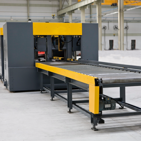
Assessing how different levels of control impact production scalability dictates your shop's output capacity. The degree of automation directly affects labor dependency, setup times, and the overall precision of the fabricated parts.
Portable, hand-held, or track-mounted units are the standard choice for field operations, maintenance turnarounds, and low-volume, high-mix job shops. Their lightweight design allows operators to bring the tool directly to the workpiece, which is essential when repairing existing infrastructure or working on elevated pipe racks. They offer flexibility and low initial capital requirements.
However, portable systems have distinct limitations. They operate at lower travel speeds compared to stationary units. Furthermore, they rely heavily on operator skill for setup, angle adjustment, and manual advancement. Inconsistent operator pressure can lead to variations in the root face. While excellent for field work, portable units become a bottleneck in high-volume manufacturing environments.
For facilities processing thousands of parts per week, a CNC beveling machine provides unmatched throughput. These systems feature multi-axis control, allowing the cutting head to manipulate complex angles and variable root faces along a single edge. Automated tool changing systems swap milling heads seamlessly, transitioning from a standard V-bevel to a complex J-bevel without operator intervention.
Integrating a CNC system into larger fabrication lines allows for continuous part feeding. The return on investment for CNC systems is realized in environments requiring complex, variable profiles on heavy plates. By removing the operator from the setup equation, CNC machines eliminate human error, guarantee absolute repeatability, and keep automated welding cells fed with perfectly prepared materials.
A beveling machine with PLC control serves as a highly effective middle-ground solution. It bridges the gap between manual track systems and full CNC integration. Programmable Logic Controllers manage the critical cutting parameters that dictate edge quality. Operators select a pre-programmed recipe, and the machine automatically sets the appropriate feed rates and spindle speeds.
PLC systems handle angle adjustments and provide real-time diagnostics, alerting operators to tool wear or motor strain. This level of automation drastically reduces operator error and ensures consistent repeatability across production batches. It provides the precision required for automated welding while keeping capital costs significantly lower than fully articulated, multi-axis CNC systems.
Matching machine specifications to facility requirements requires a structured evaluation. Selecting the wrong equipment leads to excessive consumable wear, inadequate weld prep, and production delays.
Machine torque and cutting technology must be matched to the material hardness. High-tensile materials like Hardox, armor plate, or Duplex stainless steel require heavy-duty milling machines with high-torque gearboxes. Shearing machines, while fast on mild steel, struggle with high-tensile alloys and can cause material fracturing or rapid cutter failure.
Capacity limits must be strictly observed. Buyers must verify the maximum wall or plate thickness the machine can process in a single pass. For pipe applications, sizing the machine for the proper OD/ID range is a strict requirement. Purchasing a machine that operates at its absolute maximum capacity leads to premature motor failure; equipment should be sized so that daily operations fall within 70% of its maximum rated limits.
Machine capabilities must map directly to the required weld joints to properly prep the metal seam. Standard V and Y joints are easily handled by most rotary shear and milling machines. However, heavy-wall pressure vessels often require U or J-bevels to reduce the total weld volume and minimize heat input.
J-bevels are absolute necessities for narrow-gap welding techniques. Only specific milling machines equipped with radius cutters can accurately produce J-profiles to ASME and AWS standards. If a facility anticipates bidding on high-pressure piping or nuclear contracts, the chosen machine must possess the mechanical rigidity and tooling options to generate precise, repeatable J-bevels.
The physical location of the work dictates the machine's power requirements and environmental tolerances. Stationary shop machines utilize 3-phase electric power and require significant floor space. They are designed for clean, controlled environments where material is brought to the machine.
Field-ready portable units must tolerate harsh conditions, dirt, and moisture. Pneumatic motors are highly favored in explosive environments like refineries or offshore platforms where electric sparks pose a severe hazard. Hydraulic units offer massive torque in compact frames, ideal for heavy-wall pipe in remote pipeline trenches. The operational environment directly dictates the machine's footprint and power source.
Machine Type | Primary Workpiece | Ideal Environment | Key Advantage |
|---|---|---|---|
Portable Milling | Plate / Structural | Field / Job Shop | High mobility, clean cold-cut edges. |
ID-Mounted Lathe | Pipe / Tube | Field / Fabrication Shop | Perfect concentricity, simultaneous facing. |
PLC Controlled Stationary | Heavy Plate / H-Beam | High-Volume Manufacturing | Programmable repeatability, high throughput. |
Automated Thermal Carriage | Ultra-Thick Plate (>3") | Heavy Shipyards | Rapid processing of massive thicknesses. |
Addressing setup procedures, tooling management, and maintenance hurdles post-purchase ensures the equipment delivers the expected efficiency gains.
Setting up a machine requires a methodical workflow to guarantee precision before the cutting head engages the metal. Skipping steps during calibration directly results in rejected parts and wasted material.
Measure the internal or external diameter of the workpiece to select the correct mounting hardware.
Install the appropriate expansion blocks or magnetic track clamps to secure the machine rigidly.
Set the milling head to the required degree angle using the machine's integrated protractor scale.
Adjust the depth of cut to establish the exact root face dimension specified by the welding procedure.
Execute a short test pass and verify the profile with a standard welding gauge before engaging the auto-feed.
Ongoing operational expenses are driven by carbide inserts, milling heads, and cutting fluids. High-performance carbide inserts are brittle; they excel at cutting but shatter under impact. Dropping a machine or ramming the cutter into the plate edge will destroy the tooling instantly.
Maximizing consumable lifespan requires strict adherence to speed and feed optimization. Operators must apply continuous cutting fluid or paste to reduce heat buildup when machining alloys. Rotating carbide inserts precisely when they dull—rather than waiting until they chip—ensures the machine does not overwork its motor and maintains a pristine surface finish.
Upgrading from manual grinding to mechanized systems yields a massive return on investment, but it requires specific operator training. The learning curve involves understanding chip load, reading PLC interfaces, and calibrating complex angles. Vendor-supplied training via intuitive Human-Machine Interfaces (HMIs) rapidly brings operators up to speed.
The ROI is quantified by calculating labor savings and the drastic reduction in post-weld defect rates. Mechanized prep eliminates the ergonomic strain and vibration injuries associated with heavy hand grinders. A single operator running a mechanized system can prep ten times the amount of material in a shift compared to manual grinding, with zero rework required by the welding department.
Machine downtime on the critical path of a fabrication schedule halts all subsequent welding operations. Routine maintenance is non-negotiable. Operators must clear metal chips from the gear tracks and lead screws daily to prevent binding. Lubrication of all moving parts and regular inspection of motor brushes ensure consistent performance.
Fabrication managers must maintain an inventory of critical spare parts, including extra mandrels, clamping jaws, and drive belts. Relying on overnight shipping for a broken gear can delay a massive project. Establishing a strict preventative maintenance schedule mitigates unexpected failures and extends the operational life of the equipment.
Audit your current weld defect rates to identify failures originating from inconsistent manual edge preparation.
Calculate your current manual preparation labor costs, factoring in the time spent grinding, measuring, and reworking fit-ups.
Categorize your primary materials by thickness and hardness to determine if milling, shearing, or thermal cutting is required.
Request technical specification sheets and time-studies from equipment manufacturers to compare PLC and CNC throughput against your current baseline.
A: The primary function is to remove material at a specific angle from the edge of a metal workpiece. This process creates a precise channel, such as a V or J groove, that allows for proper weld seam penetration. It ensures a structurally sound joint between two pieces of metal.
A: Cold cutting uses physical milling or shearing. It generates no Heat Affected Zone (HAZ), eliminates hazardous grinding dust, and leaves edges immediately ready for welding. Thermal bevelling uses plasma or oxy-fuel. It is faster for ultra-thick plates but alters the metal's metallurgy and requires post-cut cleaning.
A: Generally, no. While some modular systems exist, dedicated pipe bevelers and plate bevelers are standard. They require completely differing clamping mechanisms, such as internal mandrels for pipe versus magnetic tracks for plate. They also use distinct tracking mechanics to handle specific geometries accurately.
A: A PLC-controlled system offers programmable repeatability. It automatically manages consistent feed rates, spindle speeds, and angle adjustments based on pre-set recipes. This reduces reliance on manual operator adjustments, minimizes human error, and ensures uniform edge quality across large production batches.
A: Standard portable shearing machines typically handle plates up to 1.5 inches thick. Heavy-duty stationary milling machines can process plates up to 4 inches thick. For plates exceeding these thicknesses, automated thermal carriages are usually required to remove the massive volume of material efficiently.
A: Yes, especially when machining hard alloys like stainless steel or Inconel. Cutting fluids or pastes reduce friction and heat buildup at the cutting edge. This prevents the material from work-hardening and significantly extends the lifespan of the carbide inserts.


