
Views: 0 Author: Site Editor Publish Time: 2026-09-29 Origin: Site


Walk onto any modern fabrication floor, and you will immediately notice the relentless push for speed without sacrificing precision. A single misaligned hole in structural engineering compromises joint integrity. It causes severe safety hazards. Worse, it can halt an entire construction project. Fabricators constantly battle operational bottlenecks when processing complex hole patterns on H-beams. Varying web and flange thicknesses across different steel profiles only multiply these headaches.
High-speed beam drilling machines provide a highly engineered, reliable solution for processing these diverse and complex configurations efficiently. By replacing manual layout and magnetic drilling with automated CNC processing, fabrication shops drastically reduce material handling time. They also eliminate human error entirely. This comprehensive guide explores the specific hole patterns suited for these advanced machines. It details how to optimize your production floor and identifies the critical features that define reliable, high-volume equipment.
Advanced high-speed machines effortlessly process standard, staggered, and slotted hole patterns on both flanges and webs simultaneously.
Implementing 3-axis CNC technology enables true 3D drilling. This significantly reduces material handling and beam flipping time.
Integrating marking systems with your drilling setup ensures perfect alignment and traceability for complex, asymmetrical patterns.
Top-tier equipment utilizes hydraulic clamping and automatic tool changers to maintain continuous production without operator intervention.
Before diving into specific machining techniques, we must understand the market forces driving these technological shifts. Recent changes in the construction industry lean heavily toward modular assembly and pre-engineered metal buildings, commonly referred to as PEMBs. This growing trend has intensified the demand for complex, tight-tolerance hole patterns.
Steel members must now arrive on-site ready to assemble. There is zero margin for field modifications. If a beam does not fit perfectly, crane time is wasted, and project budgets bleed. Consequently, modern steel structure drilling equipment must be exceptionally versatile. It needs to transition seamlessly between web and flange processing without requiring manual repositioning by the operator.
Hole patterns are never arbitrary placements on a steel profile. They strictly dictate the structural integrity and load-bearing capacity of steel connections. Every pattern is engineered to accommodate specific stress factors. This applies whether the shop is fabricating bolted joints, heavy-duty base plates, or splice connections. Understanding the mechanical purpose behind these layouts is crucial for selecting the right machinery.
Web holes are typically utilized for shear connections. These joints are responsible for transferring vertical shear forces. These are the forces that push parts of a structure in opposite directions. A common example is the connection of a secondary beam to a primary column. Because the central web of an H-beam is generally thinner than its outer flanges, the machinery must automatically adjust its feed rate and spindle speed. This precise control prevents material distortion or tool breakage during penetration.
Conversely, flange holes are predominantly used for moment connections. These specific joints are designed to handle significant bending forces and rotational stress within the structural framework. Flanges are thicker and harder than webs. Executing clean, precise holes here requires robust spindle torque and rigid clamping. The ability to process both axes concurrently is a primary driver of modern shop floor efficiency.
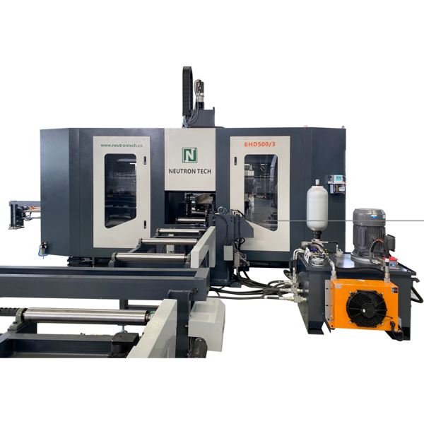
Industrial CNC drilling lines are engineered to execute a wide variety of structural layouts flawlessly. Below are the most common hole patterns processed by these machines in daily fabrication environments.
Standard grid patterns form the backbone of structural steel framing. They are primarily used for standard end-plate connections and splice plates. Imagine a massive splice connection joining two primary girders. The bolt holes must align flawlessly in perfect rectangular symmetry. High-speed CNC machines utilize multi-spindle setups to drill multiple holes simultaneously. By processing the grid concurrently, the equipment ensures perfect geometric alignment. This means the bolts will slide through effortlessly during on-site erection.
Staggered, or zig-zag, hole layouts are engineered to maintain the cross-sectional net area of the H-beam. Drilling too many holes in a straight vertical line creates a weak point. That specific point could buckle under heavy loads. Staggering the holes distributes the stress evenly across the steel member. While manually plotting a staggered pattern is highly prone to human error, advanced CNC programming reads the digital layout and plots these complex diagonal configurations effortlessly.
Slotted holes are elongated cuts essential for expansion joints. Picture a massive steel frame expanding under the summer sun. Slotted holes provide that necessary breathing room, allowing the steel to expand and contract with temperature fluctuations. They also offer crucial tolerance for alignment adjustments during field erection. Advanced high-speed machines utilize robust spindles with specialized milling capabilities to create these precise slots. They smoothly transition from standard drilling to milling without requiring a separate workstation.
Coping involves removing a section of the beam flange so it can intersect flush with another supporting member. The connection holes drilled near these coped ends demand extreme precision. Because the structural geometry at the end of the beam has been altered, lacking surrounding material support, the drilling machine must apply strictly controlled feed rates. This careful approach avoids edge tear-out and maintains the maximum load-bearing strength of the joint.
Base plates anchor the vertical H-beam columns to concrete foundations. These patterns involve large-diameter, heavy-duty holes that often exceed 30mm and penetrate thick steel sections. Executing these layouts requires immense spindle torque and rigid machine stability. Industrial drilling lines apply high-pressure internal coolant and utilize solid carbide tooling to power through thick flanges, ensuring the large-diameter holes remain perfectly cylindrical.
To help shop managers visualize the demands of different layouts, we have compiled a quick reference guide based on field data. This table outlines the primary applications and the specific machining capabilities required to execute them profitably.
Hole Pattern Type | Primary Structural Application | Critical Machining Requirement |
|---|---|---|
Standard Grid | End-plates, Splice connections | Multi-spindle simultaneous processing for perfect symmetry |
Staggered Layout | Load-bearing columns, Truss webs | High-precision CNC servo positioning to prevent net area loss |
Slotted Holes | Expansion joints, Field tolerance points | Robust spindle torque with specialized milling transition |
Large Base Plate | Foundation anchoring | Through-spindle coolant and solid carbide tooling compatibility |
To fully grasp the financial return, shop managers must look under the hood at the mechanics driving these machines. The transition from manual magnetic drills to automated lines represents the most significant efficiency leap in fabrication history.
Traditional drilling methods require an operator to process one side of a beam, wrestle the heavy steel into a new position using an overhead crane, and then drill the opposite side. A modern CNC line eliminates this massive bottleneck by utilizing three independent spindles. These are located on the left, right, and top of the processing zone. This 3-axis configuration allows the machine to perform true 3D drilling. The beam glides through the machine once, and all three spindles operate simultaneously. This drastically cuts processing time and eliminates redundant material handling.
Gone are the days of soapstone marks, tape measures, and center punches. CNC technology removes the variable of human error entirely. The machine software directly imports DSTV files exported from structural detailing software like Tekla Structures. Servo motors drive the positioning system with sub-millimeter accuracy. This guarantees that whether the shop is processing ten beams or ten thousand, the hole patterns will align perfectly during the final construction phase.
Drilling complex hole patterns is only one half of the fabrication equation. The assembly crew must also know exactly where and how each drilled beam fits into the broader structural framework. This is where processing and marking create a powerful operational synergy.
A beam marking machine is frequently integrated directly into the CNC drill line or placed immediately in-line. Before or after the drilling process, the marking unit uses a carbide stylus or plasma layout tool to print alphanumeric part numbers, heat numbers, and precise layout marks directly onto the steel surface. Traceability is a strict requirement in modern construction codes. Automating this process satisfies quality assurance inspectors while streamlining inventory management.
When dealing with asymmetrical hole patterns or beams with subtle differences in connection layouts, visual identification is critical. Integrated marking systems can scribe welding lines and attachment points for secondary plates directly onto the beam. This provides the fitting and welding stations with an exact, error-free template. It ensures that complex hole patterns align perfectly with the welded attachments down the line.
Not all drilling lines are built to the same specifications. When investing in machinery to handle diverse and complex hole patterns, fabricators must evaluate specific mechanical features based on their actual production volume and profile sizes. Let us break down what you should look for in a high-volume setup.
Vibration is the ultimate enemy of precision machining. When drilling through thick steel flanges, the rotational forces generate significant chatter. If the beam is not completely secured, this vibration can cause the hole to become oval-shaped or shatter expensive solid carbide drill bits. Top-tier machines utilize robust hydraulic clamping systems. For instance, equipment designed to process beams up to 500mm or 1000mm automatically detects the web and flange dimensions. It then applies immense lateral and vertical pressure to lock the beam rigidly in place before the spindles engage.
Complex projects frequently require different hole diameters on the same structural member. You might need to swap from a 22mm bit for standard shear connections to a 32mm bit for heavy moment connections. Implementing automated steel structure drilling equipped with an Automatic Tool Changer solves this issue completely. For heavy structural frameworks handling massive 1200mm girders, this feature is mandatory. The CNC program automatically commands the spindle to swap tools in a localized magazine within seconds, maintaining continuous production flow without operator intervention.
High-speed drilling generates extreme thermal friction that can literally melt lesser tooling. If this heat is not managed, the cutting edges of the drill bit will degrade rapidly. Advanced machines feature through-spindle coolant systems. A high-pressure mixture of air and cutting fluid is pumped directly through the center of the drill bit, exiting at the cutting tip. This effectively dissipates heat, lubricates the cutting edge, and forcefully ejects metal chips from the hole.
Even with the most advanced machinery, operational efficiency relies on applying correct machining principles. Operators must optimize tooling, parameters, and software to achieve the best results in Structural steel drilling.
Selecting the right cutting tool depends heavily on the machine capabilities and the material thickness. High-Speed Steel bits are durable and cost-effective but operate at much slower RPMs, making them suitable for older or less rigid machines. In contrast, Solid Carbide Drills are designed specifically for high-speed CNC machines. They withstand much higher temperatures and operate at feed rates up to five times faster than traditional bits, making them ideal for thick flanges and high-volume production.
Proper spindle speed and downward penetration rate are critical. When drilling through a 40mm thick flange, operators must ensure adequate feed pressure. Otherwise, the bit will merely rub against the steel, causing rapid work hardening of the material surface. Conversely, excessive feed rates can overload the spindle motor. CNC operators must adhere to the specific chip load guidelines provided by the tooling manufacturer based on the hole diameter and material grade.
The seamless flow of data from the engineering office to the shop floor is vital. Fabricators should regularly update their CNC control software to ensure compatibility with the latest versions of detailing programs. Proper software optimization ensures that digital files translate perfectly into machine code. This prevents anomalies such as incorrect coordinate mapping or skipped hole patterns.
The structural fabrication industry is facing a paradigm shift. With skilled labor shortages and tightening project deadlines, relying on manual layout and magnetic drilling is no longer a sustainable business model. Investing in automated drilling technology provides a measurable, objective return on your investment.
A single CNC beam drilling line operated by one skilled technician can comfortably outproduce a traditional team of five manual layout workers and drill operators. By automating the positioning, tool changing, and drilling processes, fabrication shops can reallocate their workforce to higher-value tasks, such as specialized welding. Furthermore, the cost of a misaligned hole is not limited to the shop floor. If an error reaches the construction site, costs compound exponentially due to crane delays and field welding modifications. The sub-millimeter accuracy provided by CNC automated systems drastically reduces these costly field reworks. This ultimately protects the fabricator profit margins and hard-earned reputation.
Modern high-speed CNC drilling machines typically hold a positional tolerance of plus or minus 0.5mm across the length of the beam. This sub-millimeter precision ensures that complex multi-hole patterns align perfectly during on-site assembly, eliminating the need for field reaming or modification.
Preventing bit breakage comes down to three factors: rigid material clamping, appropriate feed rates, and effective cooling. Ensure your machine utilizes hydraulic clamping to eliminate vibration. Always use through-spindle coolant to clear chips and reduce heat, and verify that your CNC feed parameters match the specifications of your solid carbide tooling.
Yes, most high-quality drilling lines are highly versatile. In addition to standard H-beams, they can efficiently process U-beams, C-channels, angles, and flat plates. This makes them a comprehensive solution for diverse structural steel needs.
Machines equipped with an Automatic Tool Changer can hold multiple drill bits in a tool magazine. The CNC software reads the detailing file and automatically swaps out the drill bits based on the specific diameter requirements of the hole pattern, without any manual intervention from the operator.
While stand-alone marking machines exist, many modern high-speed drill lines come with integrated scribing or dot-peen marking capabilities. This allows the machine to drill holes and mark layout lines for welded attachments in a single pass, streamlining the entire fabrication process.
While capacity varies by specific machine models, industrial-grade CNC drilling lines utilize high spindle torque and solid carbide tooling to easily drill through steel webs and flanges exceeding 50mm in thickness. They maintain perfect hole concentricity throughout the entire cut.
Staying competitive in today's demanding structural steel market requires equipment that delivers uncompromised precision and relentless speed. Whether you are processing medium profiles for commercial builds or massive girders for industrial infrastructure, having the right machinery is the difference between profit and loss. Evaluate your current production bottlenecks and explore the advanced CNC solutions available at NeutronCM. By choosing equipment tailored to your specific profile sizes and hole pattern complexities, you can eliminate costly errors, boost your throughput, and secure your position as a top-tier fabricator.


